Showing posts with label 8032. Show all posts

Sunday, 21 September 2025

SD2PET ?Device Not Preset Error

This is a problem we see every now and then.

Someone buys an SD2PET, plugs it into their PET and tries it and they get the dreaded ?Device Not Preset Error.

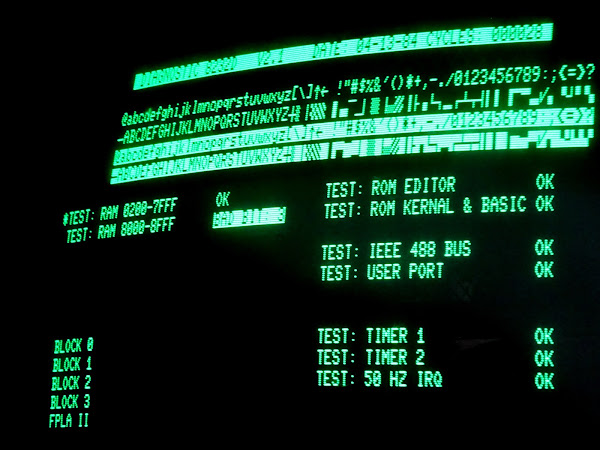
(I should apologise now as all the screen photos in this post are going to be rubbish as they are taken from an 8032 CRT and I am clearly incapable of doing that)

Now the first thought is probably "the SD2PET is faulty", but honestly, that is probably the least likely scenario.

They way I try to think of it is you are attaching a brand new bit of recently built and tested kit to a vintage computer in unknown condition.

Imagine you have a 1980 Ford Cortina. It might work fine for everything you use it for. Then one day, you need to carry more stuff around, so you attach a brand new trailer. That should go OK, but you might find it can't make it up hills any more, the tail light hookup might not work (it may never have been used before, or not this century anyway). Someone might have fitted a non-standard connector that the trailer designed to attached to a 1980 Cortina might not fit onto. The towbar mountings might be rusty and snap off as soon as you try to pull anything with it it.

None of which would be the trailers fault, but you wouldn't have known about those issues until you tried to attach one.

It may have been "fully refurbished" when you bought it, but did they try it with a trailer?

So what can you do?

Well, various things, check it's plugged into the correct connectors, the correct way up.

Check the edge connectors are clean and shinny, with no dust or corrosion or lumps of solder where someone tried to attach something sometime in the past.

Another thing to try early on is to remove the SD card.

With no SD card installed, it should return a listing of "EEPROMFS".

Until you see that, don't put the SD card back in, it just helps to narrow things down, keep it simple.

If that works without the SD card installed, check the SD card contacts or try another card.

If you don't have the TFW8b preloaded SD card, then you should get the oldest, slowest, lowest capacity card you can as that has the best chance of working. And go for an SD card, rather than microSD card in an adapter. They are not the same.

It should be formatted FAT32, although if it is formatted incorrectly (i.e. VFAT or NTFS or if it been near a Mac that has helpfully repartioned it to be unreadable), that it will more likely return "?file not found error"

If you have another PET, you can test the SD2PET on there and make sure it works (as we suspect it will).

If you have a known working IEEE-488 disk drive, you can test that out and you would expect to also see ?Device Not Preset Error.

Self Testing

The design of the PET uses two IO pins for every pin on the IEEE-488 bus (well, almost every pin, one is output only, one is input only, one is hard wired to ground).

For each of the main pins, there is an "out" and an "in", the former sets what appears on the bus, the later reads the state of the bus.

That means that the PET can actually test itself by writing to the bus and then reading back to see if that matches what was written.

I won't go into the full details here, it is described in the second half of this blog post:

If what is read back does not match, then it could be down to a few things:

  1. The output pin not sending the output
  2. The input pin not reading the input
  3. The buffer IC that sits between those and the bus
  4. Some conflicting device (bad ROM or RAM or IO chip or decoding logic - yes I know that's pretty much everything)

On the PET, the inputs and outputs are generated mostly by the 6520 nearest the IEEE-488 port, but also by the other 6520 nearest the keyboard connector and also the 6522.

The bus interface is by three MC3446 chips which connect the inputs and outputs to the bus.

If the 6520 and 6522 chips are socketed, try reseating those first, if that makes no difference, you can rule those out by swapping in known working 6520 and 6522 chips.

If that does not help, you could try something like my PET IEEE-488 Diag board (https://www.tindie.com/products/tynemouth/pet-ieee-488-diagnostics-tester/)

This shows what is happening on the bus, so it you set a signal, you can see if the LED changes. If it does, then the output side is working, but if the PEEK doesn't change, then the problem is on the input side.

If the LED does not change, you can test the input side by bridging the signal pin to ground.

Don't panic, that isn't going to damage anything. The bus should only ever be in two states. Either floating high because nothing is driving it, or driven low by the PET or the disk drive (or a bit of wire). Nothing should ever drive the bus lines high.

Note the REN LED is always on as that is hard wired to 0V inside the PET, so it's sort of a power LED, it will always be on.

Fixing the problem

On the bench today, I have an 8032 board.

The owner has gone through all the POKEs and PEEKs described in the blog post above and has found the ATN line is not reading back.

Checking that with the PET IEEE-488 Diag board, the REN LED is lit, but nothing from ATN. Everything else seems to be OK.

I tried the wire link and it did not read that back correctly, so the MC3446 is likely bad.

I thought it would be interesting to check this on the logic analyser.

I used the leads I made up recently to clip onto the suspect IC. (http://blog.tynemouthsoftware.co.uk/2025/09/logic-analyser-replacement-clip-leads.html)

I also added one on the bus, from the PET IEEE-488 Diagnostics board on the LED side so it would be 5V logic, and one on the IO chip select line, just so I could see when that was active in case both IO pins did nothing.

The results were clear, ATN out was toggling correctly, but nothing was making it to the bus.

I wrote a little test program to toggle the pin, to check.

And again, you can see ATN toggling, but nothing else.

The suspect chip is the MC3446N at UA20.

Time to get the desoldering gun out.

The desoldering gods were on my side today, that came out nice and cleanly.

A new old stock MC3446AP replaces it.

Time to retest.

Oh.

I repeated the POKE and PEEK test and it was still bad.

I repeated the wire link test and it was now reading that pin correctly. So that 3446 was bad, but there must be another problem.

I poked around with the scope and found the drive signal from the 6522 was very weak, it was only going between about 2V and about 3.5V. That's not right (but unfortunately it was good enough for the logic analyser).

The 6522 is socketed, so it was easy to try a replacement.

Ah, that looks better.

That is now swinging between 0V and 5V as it should.

And there it is on the logic analyser, Out is driving the Bus is that is being read back to In. Perfect.

But does it work?

Yes it certainly does, let's try with an SD card

Looking good

I tried a few more things, and everything seems to be working nicely.

Only the lack of dust on the new chips gives away any work has been done.

So, two bad chips, I would normally have suspected one or the other, but both have tested bad on another board.

I suspect the 3446 failed and damaged the output of the 6522, but it could have been the other way around.


Adverts

The PET IEEE-488 Diagnostics LED board is available form my Tindie store:

I can still ship worldwide.

Currently it looks like Royal Mail to the US is working without having to pay tariffs (computer parts are excluded from the 10% so there is just a handling fee, which I pre-pay). There still may be delays or charges. We're all pawns in a petulant child's political games, but we've got to just keep going and try to make this stuff work.


The SD2PET is available from The Future Was 8 bit, with optional pre-loaded SD card:


Patreon

You can support me via Patreon, and get access to advance previews of development logs on new projects like the Mini PET II and Mini VIC and other behind the scenes updates. This also includes access to my Patreon only Discord server for even more regular updates.

Sunday, 5 November 2023

PET 8032 Repair

I don't normally write up most of the Commodore PET repairs I do, because they generally follow the same patterns of RAM faults, ROM faults, and occasionally a bad CRTC. Sometimes all three.

As you might have guessed, this is not one of those.

I think I need a disclaimer.

These posts are not troubleshooting guides. They are documentation of the process I went through to fix a specific fault. They are unlikely to help in your case unless your fault has the exact same cause (not the exact same symptoms). If your PET is dead, it is most likely a ROM or RAM fault (or both). Get yourself a PET ROM/RAM board that will probably fix it. If it is a later 4032 or 8032, maybe the 6545 CRTC will also be bad, but still likely a ROM or RAM fault.

This board shows all the hallmarks of a dead 8032, no video output, no chirp. On these machines, video is generated by a 6545 CRTC chip. This needs to be initialised correctly to generate video output. If the CPU does not get to the stage of running the setup code, then you don't get a video output. Sometimes you do get a chirp, this usually means the CPU has got that far, but the CRTC chip is not working, or something is stopping it from hearing the setup commands.

Here it looks like this board has already been through the 6545 failure as the 6545 has been replaced by a 6845. That is functionally compatible, and I think has some extra features that the 6545 doesn't.

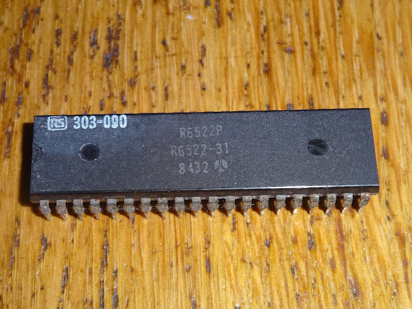
Looks like the 6522 has also been replaced, in this case with an RS part number painted on the top. They are probably out of stock of those now.

To get around the video issue, I removed the five 40 pin chips and fitted a known good 6545 and a PET diagnostics module. That will do the setup of the video chip and should generate a display.

OK, sort of progress, there is no a display, but not a good one.

Note 1 - It may look like it, but this is not a vertical sync failure, it's presumably misheard the instructions and set a very short page size.

Note 2 - I am incapable of taking decent pictures of the PET CRT. Get used to it. It's not going to get any better.

Checking the databus, you can see why it might get confused, rather than nice clean one and zeros of 5V and 0V, this is a mismash of fractions, with bits of signals at 1 and 2 volts.

I would like to have included a scope trace at this point, but I don't like running machines too long with active bus conflicts, so I didn't get any pictures that were good enough.

This is indicative of bus conflicts, and usually means several things are writing to the bus at the same time. This seems to happen a lot of the 6540-xx ROM chips and 6550 RAM chips used in the original PET, but less so with the later mask ROMs used on these machines.

The ROMs are all socketed, so time to remove them, in case it is one of those to blame.

That is better, now there is a full screen, but it's a full screen of rubbish.

Time to do some poking around with the scope.

The address lines are all wiggling around as they should be, in all the appropriate places. Due to the amount of chips on the PET board, these are buffered in a few places due to the limited number of chips the buffer chips of that era could drive. Fan out is barely an issue these days with HC logic chips that can drive a seemingly unlimited number of chips.

Pin 20 on all the ROM chips was doing odd things. These are the enable lines, and should all be high apart from the one currently selected.

But they are not.

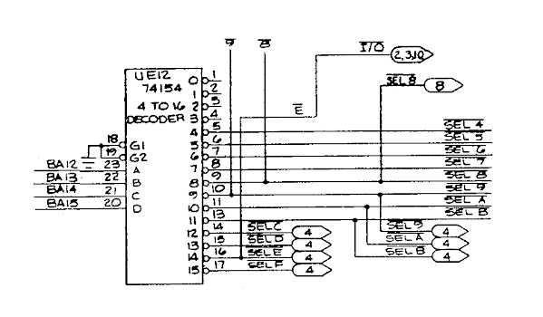
All of those are generated by the 74154 4-16 line decoder chip. This takes the top 4 address lines and generates 16 enables signals, one for each 4K block in memory. These are active low, so should normally be high with just one of them low, indicating the block currently selected.

Probing that directly, it's clear that some are high as they should be, but several are low, and a few are floating. Hmm, that's not good.

The chip fitted is actually a Mitsubishi M53354P, but I guess that's a compatible part.

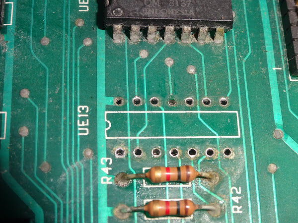
That looks a bit crusty, as do several of the chips around it. It is near what would have been a slot in the case, so is where moisture could most easily attack the board.

Even after a bit of a clean up, the legs of the 74LS10 look the worst hit, so time to remove that and the 74154 (or whatever that Mitsubishi part number was).

The traces around the 74154 look intact, but one of the traces to the 74LS10 was corroded through, so will need to be repaired (pin 11, middle top).

The 74154 equivalent failed the test, so that was indeed the main culprit.

The 74LS10 was probably OK, but the pins were too corroded to test it properly.

The 74154 is now out of production, and I am down to the last few from the last full tube I bought many years ago when they were still available.

I patched the corroded trace to the new 74LS10, which went neatly to a via above, and checked the continuity of the others.

With that replaced, I got a display.

Miraculously, the RAM all passed.

It is showing a few faults in the video RAM, but nothing visible on the screen. The timing is extremely tight on the video RAM, so much so they alternate odd and even pixels between two chips at a time as a single one wouldn't be fast enough.

The main RAM looks awful, so probably best to leave that alone if it's working.

Some people suggest washing boards like this in a dish washer. Not a fan of that idea, I am thinking about water getting trapped under chips, potential delamination of ceramic packages like those. And also, that board is pretty grotty, no way am I putting that in my dishwasher.

I started putting the chips back in, testing after each one, and it continued to work.

The only problem was one of the ROM chips.

It is showing up as empty. I checked the power pins and the enable line, and they were working correctly, so I guess the chip was just faulty.

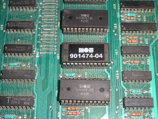
This is the only 2K ROM chip, the others are 4K, so it can be replaced by a standard 2716, or in this case, a 2816. The others need non-standard 2532 EPROMs or adapters.

The label turned out quite nicely, maybe a bit large, but I'm OK with that.

With that replaced, it passed the tests. (note, the screen shows a later run of the test with a different ROM chip, one I made with a modified keyboard table so I could use the normal keyboard on the 4032 I was testing this in, rather than the business keyboard it was expecting.)

OK, nothing left for it, time to put the 6502 back and see if it will live again.

Yay, success, we have a ready prompt.

I did a bit more testing, and all seemed fine, the IEEE-488 bus was working, after I cleaned the edge connectors, so I was able to load further games and test programs from an SD2PET.

I left it running the 8296 diagnostics program.

That again picked up the odd fault with the video RAM, but it doesn't seem to affect the screen in normal operation, so as I said before, I will leave that alone. There may be a fault somewhere in the second or third column full of chips here, but the 8032 seem to be very picky about 2114 RAM chips, so it is quite difficult to find replacements that will work.


Advertisements

PET ROM/RAM

As mentioned above, many PET faults are down do bad ROM chips or bad RAM chips, and a PET ROM/RAM chip can often help bypass those. You can order one from The Future Was 8 bit.

https://www.tfw8b.com/product/commodore-pet-rom-ram/

More info in a previous post:

http://blog.tynemouthsoftware.co.uk/2022/08/testing-pet-rom-ram-boards.html


Mini PET B

Or if you want an easier solution, the Mini PET B is a drop in replacement for a PET / CBM 40 column 32K motherboard.

More info in a previous post:

http://blog.tynemouthsoftware.co.uk/2023/10/building-a-mini-pet-b-kit.html

Mini PET B at SellMyRetro:


PET IEEE-488 Diagnostics

The PET IEEE-488 Diagnostics module is available from my SellMyRetro store, in assembled or kit form.

More info in a previous post:

http://blog.tynemouthsoftware.co.uk/2023/10/pet-ieee-488-diagnostics-updated-version.html

PET IEEE-488 Diagnostics module at SellMyRetro:

PET Diagnostics.

The PET Diagnostics modules are available from my SellMyRetro store:

Patreon

You can support me via Patreon, and get access to advance previews of posts like this and behind the scenes updates. These are often in more detail than I can fit in here, and some of these posts contain bits from several Patreon posts. This also includes access to my Patreon only Discord server for even more regular updates.

https://www.patreon.com/tynemouthsoftware