This is an old post, preserved for reference.
The products and services mentioned within are no longer available.
One of the strong points of the Commodore 64 is it's sound chip, the SID (Sound Interface Device). There are all sorts of things use can do with these, and an interesting one I saw recently in
this video from GadgetUK164, was the idea of using two SID chips, wired in parallel, to generate a sort of stereo signal. Both chips would be driven by the same digital control signals, but the outputs of SID chips do tend to be a little different, and so create a sort of stereo effect. This different is more marked if you use the version from the C64, the 6581 on one side, and one from the later C64C / C128, the 8580, on the other side.
I was concerned with wiring them directly in parallel, as the SID can be both written to and read, so when a read request is made, both chips will be trying to write to the data bus, which is not a good thing. We had a discussion in the comments on that video, and I suggested using an OR gate to generate the chip select signal for the second SID, most easily achieved in this case using a diode OR. In the
followup video, he showed the modified board, with diode OR and pull down resistor.
The inverse logic is sometimes tricky, the chip select line on the SID is active low, so needs to be low to be enabled. The read/write line is low when writing, high when reading. Here we only need the second SID to be selected when there is a write request, so CS2 is low when CS is low
AND R/W is low. Or to think of that the other way around, CS2 is high if either CS is high
OR R/W is high, hence the OR gate. A variation on DeMorgan's law.
Or as a truth table:
CS
|
R/W
|
CS2
|
SID1
|
SID2
|
0
|
0
|
0
|
Write
|
Write
|
0
|
1
|
1
|
Read
|
-
|
1
|
0
|
1
|
-
|
-
|
1
|
1
|
1
|
-
|
-
|
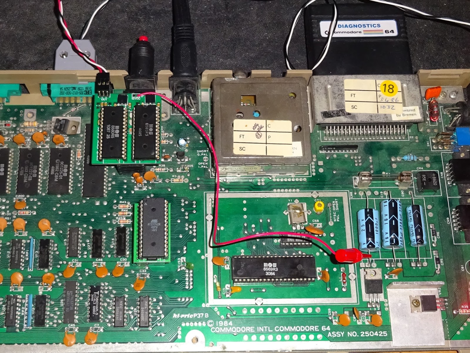
I've designed some boards which include that additional logic. The digital side of the SID remains all connected in parallel, apart from the CS line on the second SID. I've used a single gate 74HCT32 here to OR the signal. There are four parts to the analogue side. Firstly, and least important here, are the two analogue inputs, these are used by the paddle controllers on the C64. These are wired to the first chip, and there values are read when using read commands. When read commands come in, the second chip is not selected, so ignores them. The second chips analogue inputs are tied to ground. There is a jumper to also supply the second chips CS line from another source, such as one of the decoded IO address select lines on the cartridge port, for software which supports dual SIDs. Even switch between the two options should you so desire.

Second on the analogue side is the power supply. This is 12V for the older 6581 chip, and 9V for the later 8580. That confuses things a bit. The power is supplied from a 7812 regulator on the C64, and a zener diode / transistor regulator on the C64C. What I've done on these boards is ignore the supply voltage from the board, which may be 9V or 12V, and generate dedicated 9V or 12V rails for each chip with separate 78M09 and 78M12 regulators. The power for these comes from clipping onto the positive lead of reservoir capacitor C88 on the C64 board.

The C64C doesn't have that capactor easily accessible, but you can get a suitable supply by clipping onto the leg of CR3. All the chips I have tried draw around 60mA for a pair of SIDs, so this needs to be clipped onto anything that can supply 60mA at 15V-24V. When tapping power like this, it is always worth checking the voltages with a meter before using. It is also good to power up the system with the dual SID board installed and powered but no SID chips installed, and double check there is 12V on pin 28 of the 6581 socket and 9V on the 8580 socket.
Third on the analogue side are two filter capacitors for each chip. Different values are required for the 6581 and 8580, so again I ignore what is onboard and have individual capacitors for each chip. Some of the dual SID boards require you to clip off or change the ones onboard, but here I just don't connect to the onboard ones, so you can go back to a single SID if you want.

Finally comes the audio output. Here the output from SID 1 is fed through to the board as previously, so you get sound from the A/V port or TV output (is anyone still using TV output?). The outputs from both SIDs are also separately amplified and fed to a 3pin header for the stereo output. The audio output stages on the C64 and C64C were slightly different, the C64 had a capacitor bypassing the transistor from base to emitter, the C64C from emitter to ground. The board is laid out to take either arrangement, and I've been matching those to the chip, so the 6580 has the C64 version, 8581 has the C64C version. This further differentiates the stereo image.

SIDs are in short supply, and are used in various music gear outside the C64, so it is a bit luxurious to use two SIDs in one computer. However, you can use partly faulty SIDs here, I have one which locks up when you try to read from it, that is fine as SID2 here, as it will never be read. I also have a couple which have one or more voices missing. This makes the stereo a bit more varied, if a bit biased to one side or another.
The Psuedo stereo dual SID boards can be configured so each SID socket is setup for each a 6581 or 8580, independent on what was originally fitted to the Commdore 64. So you could even use this to fit a signle 6581 to a C64C or an 8580 to a C64, and leave the second socket empty.
As with the previous post on the
C64 PLA replacements, the SID is in different locations depending on the revision of the board. In some cases, the rear connectors get in the way, so you may need to stack one or two sockets to raise it up to clear the socket. I'll address that on the next revision. There are also some capacitors around, just gently lean those out of the way, or again use riser sockets.
Keyboard clearance is sometimes tight, it varies with the model, the C64C is most difficult. A SwinSID may just fit, but the extra height is right on the edge. You may have to cut or remove the metallised cardboard cover.
I'm now off to listen to more game music in glorious (pseudo) stereo.
My old favourite Spellbound (by David Jones - not that one) has great music on the C64.
Any questions? See
Commodore 64 Pseudo Stereo Dual SID Questions.
UPDATE:
There is now a new revision of this board. I have moved the second SID chip select to a jumper to the edge of the board so you can more easily wire this to one of the IO selects on the cart port, or even wire in a switch to have both options. That option is there on the previous version, but it's hidden under the chip.
UPDATE 2:
A couple of reviews:
ORDERING:
These are currently out of stock. If you are interested, see contact details above.