Showing posts with label Harlequin. Show all posts

Saturday, 3 February 2018

Keyboard options for the ZX Max 48 ZX Spectrum Clone

This is the ZX Max 48, a Sinclair ZX Spectrum 48K clone by Superfo (who also designed the Harlequin). Real Z80, ROM and RAM, and all the logic of the ULA in a CPLD.

It's a new product, I think still in development. I was contacted be a member of the Sinclair ZX World forum and asked to produce some keyboard overlays, in the same style as the ones ZX80 style overlays I do for my Minstrel ZX80 clones. He kindly sent a PCB and CPLD so I could build one.

Like the Minstrel, the ZX Max 48 board is designed to be the same footprint as the ZX81 (apart from the slightly larger edge connector and joystick port at the back).

This means it lines up nicely with the Minstrel keyboard (available from my Tindie store).

However, it was a keyboard overlay they wanted.

I designed this to fit over the ZX81 membrane, but with the ZX Spectrum keywords, symbols, colours and even the rainbow stripe.

Surprising how much smaller than a Spectrum it is, seems closer to the Horizons tape.

If you are using a ZX81 case which has a working membrane, you can stick the overlay directly over that.

Or you can get the overlays and ZX81 membranes from my Tindie store).

The overlay sticks over a ZX81 style membrane.

You then get a ZX Spectrum style membrane, which can be installed in a ZX81 case.
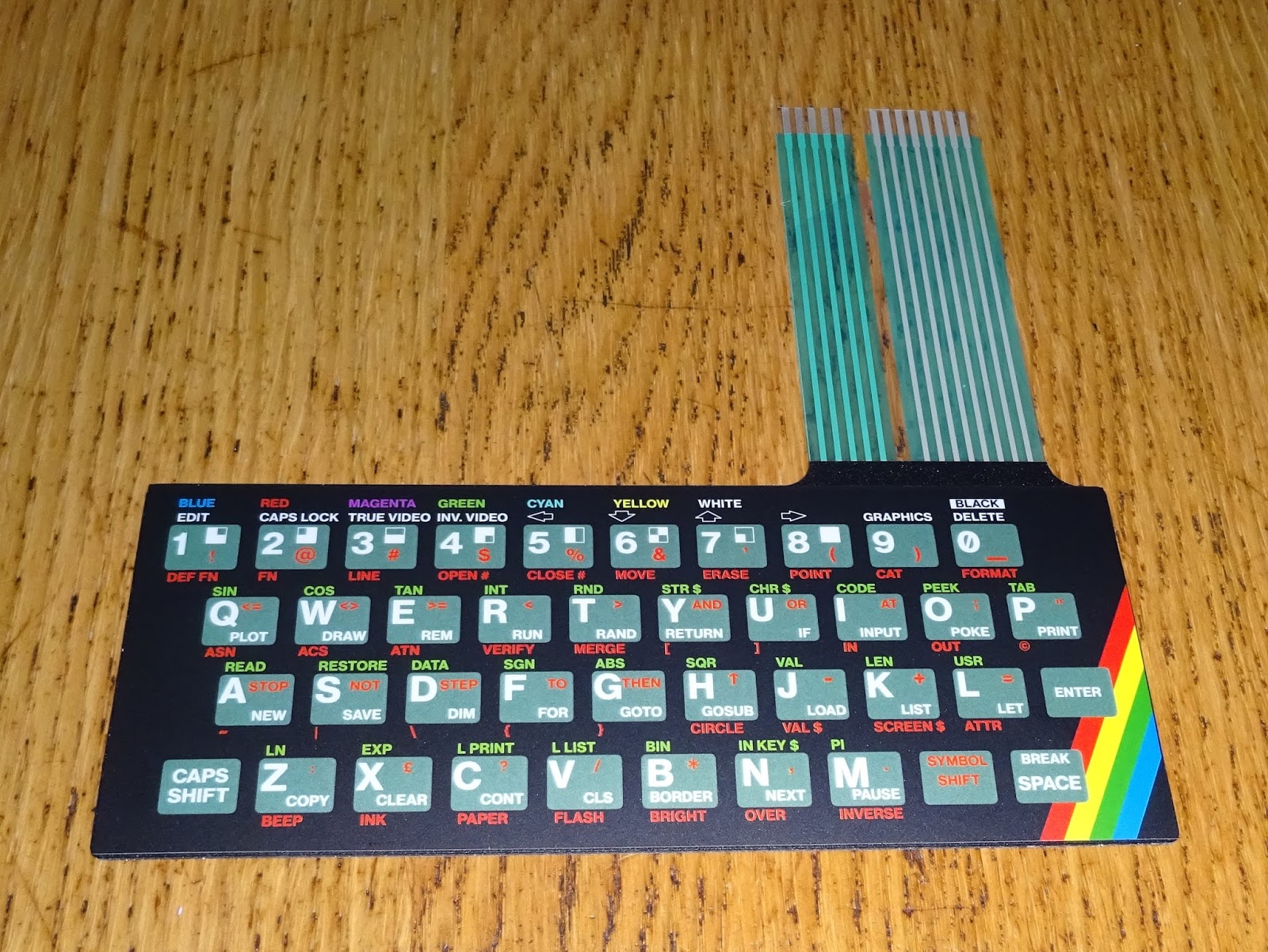
Either way, you get a ZX81 with a ZX Spectrum style keyboard.

The ZX Max 48 board will fit inside, although you would need to modify the back of the case if you wanted to use the edge connector or fit a joystick port connector.

It's a sort of slightly smaller, slightly deeper Spectrum with a less rubbery keyboard.

You don't have to use a ZX81 case, you can just mount it on a board, or a sheet of perspex.

To do this, I fit the membrane connectors under the board, so the membrane tail is hidden under the board.

It's almost worth doing this just to admire the underside of the ZX81 membrane (this version designed and produced for me by RWAP).

It's not bad from the top side either.

So a complete new Spectrum, with mainly new bits (the NEC ROM chip in the above photo is original, as is AY-3 sound chip).

Well, I suppose I should fire it up now.

It almost worked first time. I got a result with the test ROM, but in monochrome. There are two oscillator circuits, one 14MHz which is divided down by the CPLD to generate the main Z80 clock, and also 4.43MHz which is for the PAL colour burst, but that wasn't running.

I found a similar problem on a Harlequin board I repaired. That had a dodgy 74HC04 chip. I tried a few others here, including the unbuffered version, the 74HCU04 (as used on the Spectrum +2). That didn't help, so I wasn't sure what the issue was. Might have been something up with the crystals I bought. I looked at other series resonant oscillators, and the capacitor value was generally larger, so I swapped out the 100pF for 100nF on the 4.43MHz side and it came to life.

The diagnostics was now in colour and all tests passed.

Back to the original ROM, and we appear to have a Spectrum.

10 PRINT 20 GOTO 10 had to be done.

Time for a bit more testing. Yes, that is a normal sized Zip Stik. And yes, that is a divMMC future.

This is a ZX Max 48 issue 2 board, which has a Kempston joystick port build in (and an AY-3 sound chip). The divMMC future also has a Kempston joystick, so I removed the 74HC366 chip to avoid any conflicts).

Only slight issue was the divMMC future board was a little high, luckily I had the perfect thing, not the usual sort of rubber feet, but it did the job.

Jet Pac ran nicely as did most of the other things I tested. There were shimmering lines in the graphics on a couple of games, I am told there is some updated firmware, so I'll give that a go.


The Minstrel ZX80 clones and keyboards are all available from my from my Tindie store:

The overlays are still available from my from my SellMyRetro store:

Saturday, 26 November 2016

Building a Harlequin ZX Spectrum Clone

This is an old post, preserved for reference.
The products and services mentioned within are no longer available.

I've been working on a lot of ZX Spectrum and ZX Spectrum related items recently, and have now built a ZX Spectrum Clone.
The Harlequin is a clone of the ZX Spectrum using standard TTL parts. Based on Chris Smith's excellent book 'The ZX Spectrum ULA: How to Design a Microcomputer' which documents reverse engineering the Ferranti ULA within the Spectrum. The Harlequin is an implementation of that reverse engineered design, it has been around for a number of years, and currently seems to be fairly stably on revision G.
I've been tempted a few of times to buy one of the assorted bare PCB 'Harlequin' boards on ebay, but was never sure if they would work. I was then contacted by someone who had bought a kit of parts and a PCB and had built it and it didn't work, and they wanted me to fix it.
As a sweetener, also included was a second PCB and a partial set of parts they had bought intending to build a second one, but never completed. This was my fee for a successful repair, sounds like a deal to me.
The yellow board they had assembled looked OK to me, the soldering was good, the parts were all in the right place. I decided I should have a go at building the second one, so I had a reference to compare it to.
This second Harlequin, has a nice looking black PCB, and is supplied with the three surface mount parts already fitted, and a good set of instructions and a parts list. I don't normally like black PCBs, but I'll make an exception in this case, although it will make debugging difficult as you can't see the traces.
The design specified 74HC series chips, I don't normally keep those in stock. I think the original 74LS and modern 74HCT parts are better suited to repairs I do, but this is a complete unit, so the time to order a lot of 74HC chips. One part which was slightly unusual was a row of 2SA1175 'E-Line' packaged transistors, I couldn't find these from any of my usual suppliers, so had to resort to ebay. These little tester are great to check that what you have is actually a transistor, the pinout is right and the performance is approximately what it should be.
Construction was pretty straightforward, following the usual patterns of installing the smaller components first. I wanted to do this properly, so I went for decent quality new parts and turned pin sockets etc. and tried to keep things neat. I went for good old 4 band, 1/4W, 5% carbon film resistors as I have been doing those colour codes automatically in my head for over 30 years, whereas the blue 5 band ones I've always got to think twice to work out the value.
There are a few electrolytic caps on the board, and they were very specific about the lead pitch in the parts list, even two different pitch 220uF parts. I was concentrating on getting caps to fit those requirements, and ended up with ones that were the right spacing, but a bit too tall.
That's all the parts fitted now, other than the ICs. I had a good look around the board at this point to check for any missing parts or bad soldering. Yes, R37 is missing, it's optional (trimming for the tape load circuit). All OK, time to power it on. I checked around the board and the 5V rail was live, and the current draw minimal. OK, time to install all the chips.
I've gone for almost matching Texas Instruments chips all around, is that OCD? The EPROM is the one that was fitted to the other board, as this had ZX Spectrum Diagnostics on it. Time to bite the bullet and switch on.
Success! At this point I was trying not to feel smug. I failed. Smug mode on.
A quick check on the power supply, it was drawing around 116mA at 9V, looks about right, nothing getting hot.
I plugged in a keyboard and pressed 1, and let it run through the tests a few times. This was V0.32, V0.33 is now available from the ZX Spectrum Diagnostics site.
All looking good, time to switch over the Spectrum ROM chip. There are some copyright issues over the Spectrum ROM, so I have used an original chip salvaged from a dead board. With the Spectrum ROM installed, up came the normal (c) 1982 message, looks like we have a Spectrum.
Simple BASIC programs run fine, the picture is nice and clear, this is an LCD TV fed via composite video.
There is an RGB socket, but that required cutting the case and making up a custom lead, so I'll stick with the composite video for the moment.
I loaded a few games via tape and it seems to be a very good clone, everything worked as expected.
One of the reasons for building this is to test something I've been working on recently, pleased to say it ran well on the Harlequin board. More on that at a later date, for the moment I have to disguise it's identity, so I am writing this in an actors voice.
I'll need to get some alternate capacitors as the ones I fitted were too tall for the original rubber key 48K Spectrum case. For the moment, I have installed in it a Spectrum+ case and it is running very nicely.
I was planning to write up a separate blog article on repairing the other board, but it doesn't need it. The only part I had found that looked wrong was the resistor array, it was 680R, but the parts list said 470R. That shouldn't make much of a difference, so I changed it. It didn't make a difference.
It's worth noting the part number of the replacement 470R resistor array (centre) is 4116R. Not to be confused with the 4116 RAM chip (below) which would have been in the original Spectrum. I left it in as it seemed a nice touch to still have a 4116 in the Spectrum. Even with the more asthetically pleasing resistor array installed, it was still dead. There was 5V power all around the board, but no video output, and no CPU clock. I started back at first principles and check for the a signal on the 74HC04 which generates the clock.
That's a nicer clock than you would get in a real Spectrum, so that shouldn't be a problem. I traced it through the board, where it is dropped to 7MHz, and then to 3.5MHz, and checked along all the counters which generate the video sync pulses, all seemed to be fine. I checked the circuits which generate the characters, again, all looked good. By the time I got to the composite video connector, the signal was still looking fine. I turned the monitor on, and was greeted by a picture, (c) 1982 Sinclair Research Ltd.
Slightly confused, I turned off the power and swapped in the diagnostics ROM and switched it back on. Now it was dead again. I know that ROM was OK as I used it in the other board, so back to the oscilloscope. As soon as the probe touched the pin on the 74HC04, the speaker made a beep, and the diagnostics popped up on the screen.
This was repeatable, it wasn't a bad joint, it seemed the load of the scope probe was enough to get the oscillator running. I replaced the 74HC04 and tried again and it started itself and now runs fine, so all that was down to a flaky 74HC04 chip. That's packed off back to it's owner, and I'm back to playing Jet Pac on my Harlequin board.