Sunday 26 February 2023

Minstrel 4D Development Part 4 - It Flips but it won't Flop

Continuing the series of previously Patreon exclusive posts on the development of the Minstrel 4D kits.

This is one of those cases where the act of describing the problem, collecting the relevant images and scope traces is often enough to solve the problem, often before I have reached the end of the actual blog post.


I am hoping someone will be able to point out the obvious error I have made in this circuit, because I certainly cannot see it.

Yes, I spotted the "TRUBO" typo. Almost immediately upon receipt of the "Your PCB is in production" email, when it was no longer possible to correct it.

That was an easy fix as I only got a few boards made, but it is sadly not the only problem.

This flip flop sets the normal (3.25MHz) or turbo (6.5MHz) clock for the Z80. There are three inputs, /Set_Normal and /Set_Turbo come from the microcontroller, and are pulled high with external resistors so they are not triggered when the microcontroller is in reset etc. I see the same issue with and without the microcontroller present, so I have removed that for the moment, and these two inputs are just pulled up to 5V, so can be ignored.

The other input is shown in blue, a short (165mS) positive pulse on the clock input. Because D is connected to /Q, this should cause the outputs of the flip flop to toggle, but it doesn't.

Yellow and green show the Q and /Q outputs, and as you can see, when the pulse comes in from the switch they both change as expected and turbo is switched on.

The problem comes when it is time to switch them off, I can see a brief blip on the scope, but it always goes back to the previous state. This is repeatable. If turned off, it will always turn on. When on, it will never turn off.

I thought the LED might be causing a problem, so I first changed the value of the resistor down to 2K2, and finally cut it out all together, but that made no difference.

I even tried removing the onward connections of the Q and /Q signals, so there was nothing else connected to the outputs of the chip.

In those pictures, the blue probe is the third input on the scope, trigger, to show the input pulse, and that is digital, so it looks nice and clean. I know it should be clean as it is being debounced by the same circuitry that handles the power on / off switch, which is working very well.

As this is part of the power on/off circuitry, the inverter gate is powered from 9V. A simple level shifter is created with a diode and a 5V pullup resistor. When the output of the inverter is low, the diode conducts and pulls the TurboSwitch signal low. When it is high, the diode is reverse biassed, so no current flows and the pullup holds the TurboSwitch signal at 5V.

Just to be sure, I thought I would probe that with one of the analogue scope channels.

And there you go, it's not a perfect square, but it's being debounced, and .......

....hang on, that's working?

and back again.

Oh no, not another one of those things that change when you probe them.

This was indeed now working most of the time. I found that when I had both the external trigger input and the green probe on that signal, it worked.

I tried a few things and managed to capture the issue with just the green probe connected.


It looks like there is just enough of a spike at just the right time to make it appear as two clock pulses and turn it back off again.

How weird. I would not have expected that.

Now, it seems it is being "fixed" due to the capacitance of the two scope probe together on the same pin. I could fix this by adding capacitance, but I'm never keen on doing that.

Instead of that, I reduced the pullup resistor to 4K7, to increase the rise time and give a sharper signal.

That seems to have fixed it.

I have overlaid the previous pulse in red.

You can now play the game of "spot the 4K7" and know why it's there.

What of the other debounced switched you say? Well, power on/off is used directly in the 9V circuit, so no issue there, and that is working solidly and reliable. Reset is level shifted in the same way, but doesn't seem to be an issue (it may cause a second reset just after the first has started). However, I have a spare resistor in the 10K resistor array next to reset, so I will parallel that and make a 5K resistor to sharpen that edge as well. The final debounced switch is Menu, and that makes use of the internal pullup in the micrcontroller, and has not been an issue so far.


Advertisements

Minstrel 4D

The Minstrel 4D kits are shipping now, you can order one from The Future Was 8 bit - SPECIAL OFFER - £15 off the Minstrel 4D and free shipping to the USA

https://www.thefuturewas8bit.com/minstrel4d.html

More info in a previous post:

http://blog.tynemouthsoftware.co.uk/2022/08/minstrel-4d-overview.html


Patreon

You can support me via Patreon, and get access to advance previews and behind the scenes updates. These are often in more detail than I can fit in here, this post contains bits from several Patreon posts. This also includes access to my Patreon only Discord server for even more regular updates.

https://www.patreon.com/tynemouthsoftware

Sunday 19 February 2023

Minstrel 4D Development Part 3 - Auto Typing

Continuing with some extracts from of the Patreon exclusive posts during the development of the Minstrel 4D.

One of the features of the Minstrel 4D that has invited the most questions is the auto typing.

This is where the microcontroller is able to "press" keys to type onto the screen. This came about when I was working on the Minstrel 5 (that's a story for another day). I was looking into options for an SD card storage system.

Most of these involve placing a device, usually a microcontroller, onto the bus and having some code run to extend the original system to support accessing the disk drive.

I got thinking about an alternative which wouldn't require modifying the base system at all, and instead replicates the user typing the load command and pressing play on a cassette recorder.

I got quite far down the line with that on the Minstrel 5, so when the opportunity to do a 4 ½ came along, it seemed like a good opportunity to use that work.

The initial prototype of the 4D used a similar circuit to the 5. It is probably easier to start here and go onto the final version later on.

I will in fact start much earlier, with the basics of this sort of keyboard, I have written a few posts on those, so you can have a look at them if you like

http://blog.tynemouthsoftware.co.uk/2022/05/sinclair-5x8-keyboards.html

The basic premise is a 5 bit input port at address 0xFE. The inputs are all pulled high via resistors, so it will normally read as all ones.

When the keyboard is being scanned, the upper address bus is set so that one of A8-A15 is low at amy time, and each of those is connected to the rows of the keyboard via diodes. The 5 input ports create a keyboard matrix of 5x8 with these lines.

If a key is pressed, and the associated address line is low, current flows through the resistor, through the switch, through the diode and down to the address line. This makes the input of the IO port low and so a zero if read.

In order to replicate that, you can use something like a 4066. This contains 4 individual logic controlled switches which will bridge the two contacts when enabled, doing the same job as the mechanical keyboard switch, but using FETs.

That would mean you would need 40 switches, so 10 of those 4066s to control the whole keyboard, which is not ideal, plus 40 outputs to control each of those.

Thinking about other ways to do this, it became clear that some characters would need shift and another key or symbol shift and another key, so I would need to be able to press two keys at once.

I'll look at the shift keys first as that is easier as it is two keys on a single row.

In order to "press" shift or symbol shift, I am using a 74HC574, a latch with tri-state outputs. The outputs are controlled by an OR gate.

When a key is to be pressed, the address of the key on the row is latched into the 574, with the active key being low and the others high.

If the auto typing (here labelled as "fake keyboard") is enabled, and A8 is low, then the outputs of the 574 are enabled.

The diodes block a high signal from the keyboard but will allow the keyboard column line to be pulled low if the latched key was low. This gives the same result as if the mechanical key on the keyboard had been pressed.

Pressing one of the rest of the keys is essentially the same as for the shift modifier keys, but now has diodes connected to all five columns.

Only a single row needs to be selected, so that can be set using a three to eight decoder, a 74HC251.

Here the row is set by the three output (Fake_KB0-2) and that controls the selection of A8-A15 (arranged in the order of the keyboard connector), which is used to control the 574 latch.

The procedure is then:

  • Latch modifiers first 574
  • Latch key into second 574
  • Set row address on 251
  • Set keyboard enable
  • Wait long enough for the key to be registered
  • Release keyboard enable
  • (no need to reset anything else as they will not be activated if enable is high).

That was the version as implemented on the first Minstrel 4D prototype.

That all works very well, but was using up a few too many pins on the microcontroller, so I came up with a cunning plan and replaced the 574 latches with 595 serial latches.

These do a similar job, but rather than setting 8 bits and then clocking them in once, you set one bit, clock it in, set the second bit, clock that in and so on.

As before, there is one for the modifiers, and one for the rest of the keys.

Normally, the 595s would be chained together, so the data passes through each chip until all the bits required have been clocked in, then all chips are latched at the same time. In this case, I have run them in parallel. I only need 5 bits for the key and 2 for the modifier, so that means I only need to clock out a single byte to set both latches at the same time. (I need to separate chips as their enables are different)

The Row address is set on the 251 as before.

Once the clock and data latches have been used to latch in the column positions, the same lines can be reused as the row selections. The only caveat is the line which drives clock is left high, and can be set low if required, just as long as there is no low to high transitions as that would trigger the clock.

I tried this out using my usual subtle, almost invisible, modification techniques.

The next version was somewhat neater (on the final version, I turned all the diodes around so they matched the ones on the rest of the board).

Using something like a 595 shift register is of course slower as you have to clock in 8 bits of data, but in this instance, speed is not important.

Automatically loading TUTTUT takes about 35 seconds, about 3 seconds of which is typing.

Setting a keys takes less than 10uS.

Once pressed, I have to wait over 100mS to be sure they key has been read, and another 25mS before pressing another one.

These times vary, because the delay takes into account how often the key is being read - as indicated by the IO_FE_RD signal. (I later updated the code to count IO_FE_RD pulses to know when they key should have been read)

So that is the auto typing.

I started with it typing "LOAD TUTTUT", then waiting until it had loaded and then typing "TUTTUT" to run the program, but it sometimes missed the first character or two, depending on how long it takes to process the loaded file before checking the keyboard again.

To get around that, I set it to type "LOAD TUTTUT TUTTUT" at the start. It plays the file into the ear pin and the games loads. Since the load operation only took "LOAD TUTTUT" out of the keyboard buffer, "TUTTUT" is still left there and once it is loaded, it goes back to the input buffer and reads that, which runs the game.

This mechanism is also used to load the menu program. "LOAD menu menu" is typed at the start and the brief menu program is loaded. Having lots of pages of text in the menu program took too long to load, so to speed this up, the menu program only does two things.

  1. It displays whatever text is sent to it
  2. It sends back any keys the user presses

The microcontroller generates the menu pages, sends them over the "sort of rubbish spi" (see the previous post on that http://blog.tynemouthsoftware.co.uk/2023/02/minstrel-4d-development-part-2.html).

The menu program running on the Z80 displays the page and waits for the user to press a key. When it gets a keypress, it send that back to the microcontroller (also over SPI). The microcontroller can then send back another page of menu, or carry out the requested action, read the SD or start the loading process, or whatever was requested.

During testing, I had this wired up so that it typed out whatever you sent over the serial port. Since that seemed useful, I left that in, and have been using it a lot for testing. See the previous post on some Forth coding examples - http://blog.tynemouthsoftware.co.uk/2023/01/some-simple-forth-programs-for-minstrel-4D.html

I also added the option to read a .txt or .fs file from the SD card and type that in directly. It takes a while, but it's a lot easier than typing it in yourself.


Advertisements

Minstrel 4D

The Minstrel 4D kits are shipping now, you can order one from The Future Was 8 bit - SPECIAL OFFER - £15 off the Minstrel 4D and free shipping to the USA

https://www.thefuturewas8bit.com/minstrel4d.html

More info in a previous post:

http://blog.tynemouthsoftware.co.uk/2022/08/minstrel-4d-overview.html


Patreon

You can support me via Patreon, and get access to advance previews and behind the scenes updates. These are often in more detail than I can fit in here, this post contains bits from several Patreon posts. This also includes access to my Patreon only Discord server for even more regular updates.

https://www.patreon.com/tynemouthsoftware

Sunday 12 February 2023

Minstrel 4D Development Part 2 - A sort of rubbish SPI

Continuing with some extracts from of the Patreon exclusive posts during the development of the Minstrel 4D.

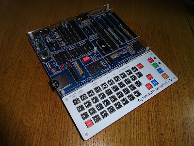
We join the proceedings as I have been modifying the first prototype board. I have wired in a microcontroller development board as I had moved around several of the pins on the microcontroller, and it also made programming and debugging easier.

There also various modifications on the right of that photo to the "auto typing" section, which will be covered in the next instalment.

July 2022

There were quite a few of the design goals of the Minstrel 5 that I carried over to the Minstrel 4th.

  • If I can keep to the unmodified ROM, I will.
  • If I can avoid conflicting with other devices, I will.
  • If I can keep the hardware minimal, I will.

One of the challenges this creates is dealing with communication between the Z80 and the microcontroller which is handling the SD card and other things. 

A Microcontroller?

First off, lets just agree we need a microcontroller. It would be possible to bit bang the SD card interface, but the processing and memory overheads would be a lot for the Z80 and there would be extensive ROM modifications required. It's not impossible, the divMMC does effectively that. But I'd rather not go down that route. 

Lets hope I am not back here in 6 months time when we still can't get any microcontrollers and I give up and go down that route (luckily I wasn't. We had to order two slightly different types, from different places, to get enough to make the full batch of kits, but we got there in the end)

Parallel

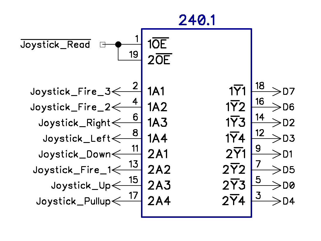
This is the normal way for something like the Z80 to interface with a peripheral. Simple IN and OUT instructions read and write to one of the 256 IO addresses on the Z80. 128 of these are wiped out on the Jupiter Ace as it's minimal decoding only uses A0 being low, so ties up all even addresses from 00 to FE, even though only FE is ever used. The Minstrel 4th and 4D fully decode this as FE to free up the other 127 addresses. The Boldfield joystick I looked at previously uses decoding of A0 being high, so ties up all the odd addresses, another 128 gone. Again, the 4D minimises this to the only address used (01), so that the entire address range is not take up by two 6 bit ports.

The Z80 read and write cycles are very fast. There's you data. There's your select line. There's your write pulse. And then it's gone. The problem here is the microcontroller isn't fast enough to deal with that in software. 

Even more so with a read, where the Z80 expects the data to be available shortly after it sets the address and read signals. Here the microcontroller is unlikely to be able to get data onto the bus in time (and just as important, to remove it from the bus before the next address is selected). And that leaves no time to work out what data it should be putting on the bus in the first place.

Maybe when you are working with 20 to 50 times faster clock cycles then you have a chance, but it's still quite tight in software to be able to deal with a write from the Z80, without hardware assistance. But with a 16MHz microcontroller and a 6.5MHz Z80, you have no chance.

Some Microchip microcontrollers have a parallel slave port. This is I/O that is designed for this scenario, and will latch data on a write, and set prepared data on a read. The ZXpand used this technique. It has a few downsides, there is no corresponding address latch, so if you have more than one address, you need to latch that separately to know what the data refers to. 

This single read /write address, leads to the slightly awkward double cycle reads. For example, the ZXpand joystick. First you write telling it you want to read the joystick. The microcontroller see this, reads the joystick, puts the value into the parallel slave port buffer ready,  and then the after a suitable delay, the Z80 reads the port and gets the value.

This is only available on a few Microchip microcontrollers, but not any recent ones, or any of the Atmel range that I am more familiar with.

Parallel with a VIA or PIA

One option I considered for this was to use something like an 8255 or a 6520/1/2 PIA. This provides a Z80 friendly interface to several ports, which can be set up to provide similar functionality to the parallel slave port, but with several real ports that can be read or written by the Z80. 

That is a bit limited, and also adds a 40 pin PIA chip and associated parts. Also needs more microcontroller pins to interface to the PIA ports.

This is sort of how the Tube works on a BBC micro, so peripherals such as the Torch Z80 board used things like a 6522 and 8255 to do the Tube interface instead of the custom Acorn part.

Serial

One idea that I initially looked at for the Minstrel 4th SD card project back in 2020 was using serial. I had a Z80-SIO dual UART, with one port providing an external RS232 interface, and the other wired to a microcontroller serial port.

This simplified a lot of the interfacing as both ends could reliably talk serial either polled or interrupt driven, and all would be neatly handled by the serial interface, the Z80 and microcontroller could just throw bytes back and forth.

If I had not had to shut everything down in 2020, I would probably have completed that along those lines.

The downside of this is the 40 pin Z80 SIO and support components.


A Sort of a rubbish SPI

The solution I have come up with is a sort of rubbish implementation of SPI, the Serial Peripheral Interface. 

SPI has four parts.

  • Clock - Generated by the master, new data is transferred on each clock pulse.
  • MOSI - Master out, slave in. Data sent from the master to be clocked into the slave.
  • MISO - Master in, slave out. Data send from the slave to be clocked into the master.
  • Chip Select - Indicates which salve device should respond, also used to indicate start of a byte. You can sort of dispense with that if you are only talking 1:1, although you will have to deal with synchronisation.

When I was designing the Minstrel 5, I worked out I had all the bits I needed to do that. Here on the Minstrel 4D, the same is true.

Clock - The Z80 is in charge. I am using the decoded IO_FE_Write line as the clock. This is activated whenever port FE is written to. This is used for two purposes on the 4D, one is for save and the other as part of the speaker. It is a very short pulse, but should be long enough to trigger an interrupt.

MOSI - As part of save, the IO_FE_WR line is used to latch D3 to provide the save signal. Think of it as a single bit IO port. 

(note, some of the schematics show this as D0, but it has been confirmed in both ROM code and PCB tracks on the Jupiter Ace, all use D3)

MISO - The ear bit on the keyboard input can be read by the Z80. There are two spare bits, but that would involve changing the 365 hex buffer for a 245 octal buffer or something like that.

Chip Select - I haven't used this. It could have been done with an extra flip flop. Instead I have handled synchronisation in the protocol.

Now, I said this is rubbish, this is because the timing is wrong to be proper SPI, so I cannot use a hardware SPI port on the microcontroller to talk to it. It also means that the logic analyser will have a good go at understanding the SPI, but will make mistakes.

Clock, this is not going to be consistent, there will be gaps between bytes that vary depending on what is happening, even gaps between bits may be consistent. Since this is a purely synchronous protocol, that doesn't matter other than messing up the display in the logic analyser.

MOSI, when writing, the clock pulse comes before the 74 latch updates. This is not a problem in practice as the microcontroller will first detect the pulse (as an interrupt), and by the time it gets around to reading, the bit will have been set. It is just about good enough to be understood by the logic analyser.

MISO, the timing is very wrong here. The way I have done it is the IO_FE_WR is followed by an IO_FE_RD to read the bit from the ear port. For the same reasons as the parallel port, it's going to be tricky to get the microcontroller to write the next bit on the clock change. So what it does is wait for the clock pulse, which will read the previous bit. It can then change the bit ready to be read on the next clock pulse.

It appears the microcontroller is doing the Two Ronnies "Answering the Question before Last" sketch.

Here you can see the ear signal changes after the write/read signals have completed, but is ready in time for the next pair. The logic analyser is one bit out, so reads 26 instead of 4D.

This thoroughly confuses the logic analyser (and also the developer). The first time I tried this, I over compensated in the wrong direction, and so this slightly odd pattern is because each bytes starts two bits too late, so it appears to step up in fours.

The protocol used to talk between them includes synchronisation, so I just wait until they are in sync and then the data continues correctly.

During testing, I did noticed the odd character was wrong. I was fairly confident the overhead of the C interrupt routine on the microcontroller would mean it was not writing until after the write / read pulses, but also that the Z80 side took long enough that the data was ready before the next cycle.

Here what should be a space (0x20) is showing as £ sign (0x60). Other erroneous characters on other screen also had bits set when they shouldn't have or vice versa.

It turned out the problem was caused by the interrupt on the Z80, which is the 50Hz screen interrupt used to read the keyboard etc. If this happened between bytes, it was fine.

The problem only occurred occasionally, when the interrupt was between the write and the read and the next bit was different to the previous one. The microcontroller would set the next bit ready, not knowing that the Z80 had yet to read the previous one, hence 0110 instead of 0010.

You can see all the other bits the value of Tape Out (MISO) changes after the read and write. This one happened on the first bit of the byte. The write goes out and the value is changed, but the read does not happen until after the interrupt, so it reads a 1 instead of a zero.

This turned a plain r into an inverted r.

Once I had confirmed that was the cause, it was simply a case of disabling the interrupts on the Z80 when receiving data. The protocol is set up as challenge-response, with the Z80 in charge, so it always knows when this is happening.

Disabling the z80 screen interrupts when receiving data has fixed that, no more interruptions to the flow.

Forth vs Z80 Assembler

As an aside, whilst developing that, I wrote the initial test code at the Minstrel 4D end in Forth. My first test took about 10mS to send a byte of data.

I tried rewriting it in Z80 to see how much faster that would be. I was rather disappointed to find to too k 60uS (yes, the units are correct, 60uS vs 10,000uS).

(n.b. I wrote both bits of code and I am not the best Forth programmer, or the best Z80 assembler, so neither may be the most optimised, but that should still be a reasonable comparison)

Have to say, I was expecting better. I was not expecting it to be many hundred times slower for a bit of simple maths and IO.

(on reflection, I was using a multiply by 2 which might have slowed things down, I am used to compilers converting that to a shift, since that is not available in the native language. I should have used an add. 

Hang on, let me try that. Back in a minute..... 

You still there? 

OK, I tried replacing 2 * with DUP +, and it now takes 8mS, so a bit better, but not much)

The Z80 assembler version all seems to be working well, so that is another thing crossed off the list. The Minstrel 4D is coming on well.


Advertisements

Minstrel 4D

The Minstrel 4D kits are shipping now, you can order one from The Future Was 8 bit - SPECIAL OFFER - £40 off the Minstrel 4D and free shipping to the USA

https://www.thefuturewas8bit.com/minstrel4d.html

More info in a previous post:

http://blog.tynemouthsoftware.co.uk/2022/08/minstrel-4d-overview.html


Patreon

You can support me via Patreon, and get access to advance previews and behind the scenes updates. These are often in more detail than I can fit in here, this post contains bits from several Patreon posts. This also includes access to my Patreon only Discord server for even more regular updates.

https://www.patreon.com/tynemouthsoftware