
Continuing the series of previously Patreon exclusive posts on the development of the Minstrel 4D kits.
This is one of those cases where the act of describing the problem, collecting the relevant images and scope traces is often enough to solve the problem, often before I have reached the end of the actual blog post.
I am hoping someone will be able to point out the obvious error I have made in this circuit, because I certainly cannot see it.

Yes, I spotted the "TRUBO" typo. Almost immediately upon receipt of the "Your PCB is in production" email, when it was no longer possible to correct it.

That was an easy fix as I only got a few boards made, but it is sadly not the only problem.

This flip flop sets the normal (3.25MHz) or turbo (6.5MHz) clock for the Z80. There are three inputs, /Set_Normal and /Set_Turbo come from the microcontroller, and are pulled high with external resistors so they are not triggered when the microcontroller is in reset etc. I see the same issue with and without the microcontroller present, so I have removed that for the moment, and these two inputs are just pulled up to 5V, so can be ignored.

The other input is shown in blue, a short (165mS) positive pulse on the clock input. Because D is connected to /Q, this should cause the outputs of the flip flop to toggle, but it doesn't.

Yellow and green show the Q and /Q outputs, and as you can see, when the pulse comes in from the switch they both change as expected and turbo is switched on.

The problem comes when it is time to switch them off, I can see a brief blip on the scope, but it always goes back to the previous state. This is repeatable. If turned off, it will always turn on. When on, it will never turn off.

I thought the LED might be causing a problem, so I first changed the value of the resistor down to 2K2, and finally cut it out all together, but that made no difference.

I even tried removing the onward connections of the Q and /Q signals, so there was nothing else connected to the outputs of the chip.

In those pictures, the blue probe is the third input on the scope, trigger, to show the input pulse, and that is digital, so it looks nice and clean. I know it should be clean as it is being debounced by the same circuitry that handles the power on / off switch, which is working very well.

As this is part of the power on/off circuitry, the inverter gate is powered from 9V. A simple level shifter is created with a diode and a 5V pullup resistor. When the output of the inverter is low, the diode conducts and pulls the TurboSwitch signal low. When it is high, the diode is reverse biassed, so no current flows and the pullup holds the TurboSwitch signal at 5V.
Just to be sure, I thought I would probe that with one of the analogue scope channels.

And there you go, it's not a perfect square, but it's being debounced, and .......
....hang on, that's working?

and back again.
Oh no, not another one of those things that change when you probe them.
This was indeed now working most of the time. I found that when I had both the external trigger input and the green probe on that signal, it worked.
I tried a few things and managed to capture the issue with just the green probe connected.

It looks like there is just enough of a spike at just the right time to make it appear as two clock pulses and turn it back off again.
How weird. I would not have expected that.
Now, it seems it is being "fixed" due to the capacitance of the two scope probe together on the same pin. I could fix this by adding capacitance, but I'm never keen on doing that.

Instead of that, I reduced the pullup resistor to 4K7, to increase the rise time and give a sharper signal.
That seems to have fixed it.

I have overlaid the previous pulse in red.

You can now play the game of "spot the 4K7" and know why it's there.

What of the other debounced switched you say? Well, power on/off is used directly in the 9V circuit, so no issue there, and that is working solidly and reliable. Reset is level shifted in the same way, but doesn't seem to be an issue (it may cause a second reset just after the first has started). However, I have a spare resistor in the 10K resistor array next to reset, so I will parallel that and make a 5K resistor to sharpen that edge as well. The final debounced switch is Menu, and that makes use of the internal pullup in the micrcontroller, and has not been an issue so far.
Advertisements
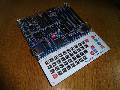
Minstrel 4D
The Minstrel 4D kits are shipping now, you can order one from The Future Was 8 bit - SPECIAL OFFER - £15 off the Minstrel 4D and free shipping to the USA
https://www.thefuturewas8bit.com/minstrel4d.html
More info in a previous post:
http://blog.tynemouthsoftware.co.uk/2022/08/minstrel-4d-overview.html
Patreon
You can support me via Patreon, and get access to advance previews and behind the scenes updates. These are often in more detail than I can fit in here, this post contains bits from several Patreon posts. This also includes access to my Patreon only Discord server for even more regular updates.
https://www.patreon.com/tynemouthsoftware
