
I am going to post some extracts from of the Patreon exclusive posts I wrote during the development of the Minstrel 4D.
June 2022
Continuing the development of the new Minstrel 4D, the first PCBs have arrived.
This is the first prototype of the Minstrel 4D. Using version number 4.5, to go with the code name of "Minstrel 4 and a half", since it was part Minstrel 4th and bits of Minstrel 5.

Keyboard
This first thing I did with this was try out the keyboard to see how that was going to look. The idea was to do something along the lines of the Mini PET deluxe keyboard.

I had thought that would look good in green.
I was wrong.
Luckily, I had forgotten to add the markings above the keys on the top row, so I had added a second overlay design to the order, whilst it was still in production, this time in white.
This caused quite a delay and a surcharge of about £5 per board, even though the green ones with exactly the same spacing had gone through OK.
The white keyboard does indeed look better.

I had designed two sets of artwork for the keycaps. I liked the idea of a black and white theme, so tried both combinations.

I think I prefer the black keys, but the poor space key looks a little lost. TFW8b suggested I move it, and I've mocked that up and I agree.

I am not happy with the font, I will probably redo these in a more generic sans serif font. I think it's a bit too stylised.

I was interested to try illuminating some of these buttons, and had moved two of the LEDs next to the keys, with that purpose. They were a little tall to fit with the 8mm standoffs used for the keys. I did try various arrangements of 3mm LEDs and 5mm LEDs on their side, but they didn't seem to even hint at lighting up the keys.
I was all set to move the LEDs back in board, when I thought I would try something else. I drilled two holes in the keyboard PCB in line with the LEDs.

That worked better than expected, I love that style. It is staying.

This is looking good, but I will again cheat what it should look like with the alternate space key position.

Testing

I built up the complete board, with all the normal parts and sockets for all the ICs. I only used a single RC2014 connector at this stage, I am unlikely to need more on this revision. Let's face it, we all know it is not going to be the final revision.

That's why I built the keyboard with the less nice yellow switches.

Side note, I still don't know why a few of the switches in each bag have the top of the plungers painted black. I just put them aside and use them on test boards etc. in case they are in some way different. In the kits, we normally use the yellow switches for power / reset etc. as you want more of a click on those, and use the white soft touch ones for the keys you type on.

Power
I had decided to try out 5V USB power on this board. See several blog posts on power input options:
http://blog.tynemouthsoftware.co.uk/2022/08/power-supplies-of-the-8-bit-generation.html
http://blog.tynemouthsoftware.co.uk/2022/10/minstrel-4d-power-options.html

I have continued the styling I used on the REDACTED boards, with things grouped in boxes, I think it is working well.

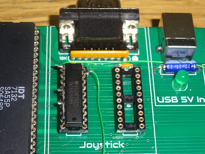
The only chips I initially fitted were these two CMOS chips, powered by the permanent supply, as on the Mini PET. One is a 40106 schmitt trigger inverter that debounces the four function keys, the other is a 4013 flip flop which toggles the power on and off.

The MOSFET at the back of the board switches the power on and off based on the output of that flip flop.
I plugged the board in and the USB 5V In LED lit dimly, as expected, and the power LED was off. Checking around the board, all the power rails were low, and the overall current draw was about 2mA.
I pressed the power button and the power LED lit up. Checking the voltages around the board, it was near enough 5V. All good.
I pressed the button again and it turned off and I repeated that a few times and it all seemed to be working correctly. I wasn't sure if I would have to adjust the RC values of any of the debouncing circuits to run from 5V rather than 9V, but all seemed happy.
Video

I thought I would start with with video circuitry. This was very much stand alone, and a straight lift from the Minstrel 4th. It is isolated by the dual port video RAM, and will give an output without the rest of the board. The only changes here were using two DIP switches to select PAL/NTSC and Normal / Inverse video, in place of two jumpers in the previous version.

Black snow is good at this point because it is reading the random data from the uninitialised video and font RAM. Everything else seems to be working. Excellent, I haven't broken the video side of things.
Clock
Next up I added the parts for the Z80 single board computer side of things, the CPU, ROM, RAM and associated decoding.

I fitted those and powered up, but just got the black snow again. Checking around the board, there was power, and a reset pulse, but no clock.
As part of the plan to remove the jumpers, I had removed the 3.25MHz/6.5MHz jumper to set the Z80 clock. The original Jupiter Ace always ran at 3.25MHz, but for the Minstrel 4th, I added the option to use the 6.5MHz clock, since that was already present on the board, and all of the parts were more than capable of that speed. I was going to use a DIP switch to switch between these options, but I thought I would make use of one of the function keys on the side, in the same way as the 40/80 switch on the Mini PET.

The complication was how to select the clock. I could have used some 74HC157 gates, or maybe a 4066 or 4052 or something like that? There was nothing like that already on the board, and I didn't really want to add an extra chip.
I had come up with an arrangement of spare logic gates to combine the two clock signals, but it wasn't working. There was no clock. Can you spot the deliberate mistake?

Looks like I messed up the logic (I was not at my best when I put together this prototype, but it was only ever meant as a starting point anyway). The disabled NAND gate is going to output high, so the OR gate will always output high. Hence no clock.
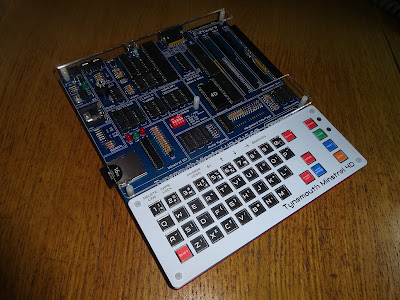
At this point, I thought I should get some pictures of the complete board, because once I start modifying things, it will never look this pristine again. Here it is with all the chips populated, just missing the extra RC2014 sockets, but you get the idea of what it could look like.

And so begins the modifications
To try to fix that with minimal changes to the board, I came up with a couple of options. First was to replace the NAND gates with AND gates, but I went with something a little more complicated. I had worked out that rearranging things I would be left with some OR gates and a single 4 input AND gate, so I came up with a plan to replace the 74HC00 chip with a 74HC32, and the 74HC32 with a 74HC08.
This way the logic would work, the NAND gates would become OR gates and the OR gate would be an AND gate. It would break anything which used the other gates in those packages, but it will at least prove the clock works. This picture shows the board slightly later on, with those chips swapped and the first few bits of green kynar wire already visible.

And indeed it does work rather nicely. The yellow trace shows the output of the "Turbo" flip flop, and you can see the clock switches cleanly on the transition.

But what about the other gates? well, the other two NAND gates were part of the 0xFE IO address decoding. Two of the OR gates were used as part of the auto load, which I was planning to change, and one for the joystick, which I didn't need yet.
I had been considered changing the IO address decoding anyway. I liked the way grouping things into neat boxes had been going, and the decoding for the joystick had worked out quite neatly, just a 688 comparator to select the address and some OR gates to generate the read signal only when the address is valid, it is an IO request and the joystick has not been disabled.

The FE decoding looks so much neater and easier to follow like this, and saves at least one chip.

I modified the 688 chip that was meant for joystick decoding to do FE decoding, I can fit the joystick later once everything else is working.
OK, so the clock is working, and we have IO and power. Lets give it a go.

Yes, white screen with a black dot.
I tried vlist but was rather disappointed to find I had messed up the keyboard as well. Rather than V, it was typing a space. Rather than L, I was getting J, I worked. S gave F and T gave Q and enter gave H. Oh dear, somewhere along the line the columns has been reversed. I "fixed" that by rewiring the data lines on the 367.

Success, with four of the data lines swapped, they keyboard was now reading correctly.

And there is the VLIST command that no post on a Forth based machine would be complete without.
The keyboard was all working correctly, but later in testing I found a weird anomaly. The "Delete line" key combination wasn't working. Shift + 1 should delete the current line. Further investigation found that shift + anything in that column wasn't working, likewise, symbol shift and anything in the same column as it. How odd. This reminded me of a problem you occasionally see with the ZX Spectrum, where the keyboard mostly works apart from SHIFT + A which should give STOP, but doesn't. The solution in that case is to change the 10K pullup resistor to a lower value, and with a temporary bodge that did indeed fix the issue here.
(There was a whole separate post about this issue, which I posted last week - http://blog.tynemouthsoftware.co.uk/2023/01/odd-keyboard-issues-or-my-spectrum-wont-stop.html)

It seems that the address line, via a diode, pulled up by that resistor is not recovering back to the high state fast enough. It was fine at 3.25MHz, but only a problem at 6.5MHz. I considered three options:
- Reduce the pullups to 6K8 or 4K7. Maybe an option, but I didn't really want to increase the loading on the address lines, although the modern CMOS Z80 chips should be more that capable.
- Buffer the address lines, in a similar way to the ZX81 external keyboards (see previous post). Potentially with an option to only enable the buffer lines on a read? That would have added a 244 or 245 and would still have needed the diodes to avoid shorts. Not ideal, I am trying to reduce the number of parts.
- Since the problem was due to not reaching the level for a logic 1, why don't I just reduce that requirement?
The original plan was the use a 74LS365 for the keyboard IO interface. The rest of the board was 74HC, but I had gone for LS here to reduce bus contention with external keyboards on the RC2014 bus. It should also help loading from tape as it reduces logic levels there as well. However, I had other plans for the tape input, so I had built this one with a 74HC365 to keep it all 74HC.
I tried fitting a 74LS365. The columns were back to being in the wrong order, but with some deep concentration, I was able to work out what keys I should press, and it appeared to be working, so I repeated the modifications on the 74LS365. With that rewired, SHIFT+1 was still working, so I guess I am going back to using a 74LS365.
Loading a game
I am adding my own SD solution, but I know that will need some work, so just to get started, I tried the Jester Ace. I wanted to be sure that would still work, and that was also a good test of the RC2014 interface.
It didn't work.
The status LED was remaining red, as it if didn't have an SD card. I went through various theories, including not enough power via USB, something conflicting on the bus etc.

I set it on on a backplane with ribbon cable connection and plugged it into a Minstrel 4th, and re-tested it to see it was still working on the normal 4th, and it was fine. The red LED flashed and then the green one came on.
With the ribbon cable connections, I could choose which pins to wire up, so I went back to the Minstrel 4D prototype and started with just the power connected.
That worked, red flash, then green on.
I added more cables, and eventually the whole top 20 pins, and kept trying it as I was going and it kept working (the soft power button was very handy for this). It appeared to stop working when I got to the databus?

I started adding the data bits one by one, and when I had added all 8, it was still booting. But when I went back to the full 40 wire bus it wasn't?
After a lot of head scratching, I noticed the reset pin of the micrcontroller on the Jester ACE board was wired to pin 40, one of the spare pins on the RC2014 bus.

That wouldn't normally be a problem, those are "spare" pins. I had just happened to wire those "spare" pins to ground when I was testing so I had somewhere to put the ground leads of the test wires.

With that removed, it booted, and I was able to continue with the testing.

Of course, I went for TUT-TUT, credit to David Stephenson for a great game and to George Beckett for an equally great port.

That is all running nicely, I had to load at 3.25MHz due to a limitation with the Jester Ace, but I can switch to 6.5MHz using the turbo button to make the mummies move at double speed and the music sound too fast. I will try some of the games with 6.5MHz support once I have the alternative loading methods sorted (there are issues with those games and the Jester ACE anyway - see a previous post on that).

OK, so that is basically a recreated Minstrel 4th.
Lets add the new stuff.
Joystick
The joystick address decoding needed quite a bit of rework. The OR gate it used was no longer available, and it's 688 socket already had a chip in it doing the FE decoding. I piggybacked another 688 on top to do the 1F decoding (the joystick was Kempston compatible at this point - Boldfield came later) and wired in a 74HC32 OR gate on top of the 240 buffer chip to balance things out a bit.

There is no direct support for a joystick, but it's fairly simple to implement in a few lines of Forth.

Initially that wasn't working.

I was getting 64 back when nothing was pressed, and only up, down, left and fire 1 were registering?
I wasn't sure what was going on there, so I left it for a while and woke up at 3 AM the next morning having remembered that there are two separate enable lines for the 74HC240 chip I was using, and I had only attached one of them to the 74HC32 lash up on top. With that wired up, I got 0 at rest and all the directions now worked.

I noticed there is a bit of snow when this is scrolling fast, you can just see a black line on the top right of the screen in that photo. I need to check that out, the video RAM should halt the Z80 for a cycle or two on the odd occasion where the address that both sides wants to access is the same. More investigation required. (there was a lot of investigation - I will post a condensed summary next week)

There is also a spoiler in there for the future of the power input.
I will leave it there for now. The next step is a big one, it is the Minstrel SD and related items, and that is definitely a big post on it's own.
One of two modifications may have taken place, but it's fine, I have used green wire, so you can barely see them...

Advertisements
Minstrel 4D
The Minstrel 4D kits are shipping now, you can order one from The Future Was 8 bit - SPECIAL OFFER - £40 off the Minstrel 4D and free shipping to the USA
https://www.thefuturewas8bit.com/minstrel4d.html
More info in a previous post:
http://blog.tynemouthsoftware.co.uk/2022/08/minstrel-4d-overview.html
Patreon
You can support me via Patreon, and get access to advance previews and behind the scenes updates. These are often in more detail than I can fit in here, this post contains bits from several Patreon posts. This also includes access to my Patreon only Discord server for even more regular updates.
https://www.patreon.com/tynemouthsoftware
