Showing posts with label PSU. Show all posts

Thursday, 9 October 2014

Commodore 128 Repair - Part 1 PSU

This is an old post, preserved for reference.
The products and services mentioned within are no longer available.

Here we go again, it's not long since I finishing the repair / rebuild of one of Commodore's first 8-bit computers, the Commodore PET. Now I'm tackling their last 8-bit computer, the Commodore 128.
This one doesn't look too bad, a bit of yellowing on the keys and some marks on the case, but otherwise intact. The power supply has a few issues, so before I began, I gave it an initial checkout, and a short run with an Amiga 500 power supply. The Amiga supply uses the same connector, and two of the pins are the same, 0V and 5V. The Amiga PSU's 5V is rated at 4.3A, the C128 was only 2.5A, so it should be fine. The other two pins are 9V AC at 1A on the C128, and +/- 12V on the Amiga. It works well enough to get the welcome screen, but not recommended for normal use.
The PSU that came with this C128 was taped together, the plastic pillars having snapped. The mains plug was European, that would need to be changed, but since the mains cable was also damaged at the input, I'll just go for a replacement cable.
Inside there were a few more problems. With that replaced, there was no output on either the 5V DC or the 9V AC side. Checking further, the 1.4A fuse on the AC side was blown, and the large inductor in the centre was loose.
Although held in place with a cable tie, both solder joints had cracked, and it was wobbling around. This is the main output inductor on the 5V supply, hence no output. With the fuse and mains cable replaced and the inductor re-soldered, I fired it up and found the 9V supply was there, but the 5V was about 4.5V. There was an adjustment, so I trimmed that for 5V again.
I was hoping I'd be able to replace half or all of the case with one from an Amiga 500 PSU. There were a number of models, all the same shape and size. The original 'heavy' linear one is on the left, the 'light' switch mode one in the centre and the C128 on the right.
It looks like the screw holes are in different places on each one, so I won't be able to do that. I'm not happy with the case of the C128 PSU, so I may put that to one side and look at making a new PSU by adapting one of the A500 ones. All I need to do is disconnect the +/- 12V and install a small 9V 1A transformer. That way I'll get a solid case and a mains switch. The original C128 supply will do for the moment, now onto the main unit....

Thursday, 2 February 2012

Universal Laptop Power Supply Further Update

This is an old post, preserved for reference.
The products and services mentioned within are no longer available.

After using this for a while, I've made a few changes. The power LED was wired in place of the original on the unit and wasn't ideal. As there is a delay in starting, it doesn't light immediately, and if there isn't much load it doesn't go off immediately. The combined with a possibly dodgy mains switch led me to make a change. I also thought a couple of 4mm posts would actually be a good idea, to make the unit more general purpose, so time for a bit of rework.

I added the 4mm posts and a new 'output on' LED wired across those (well almost +V is taken from the input side of the ammeter so as not to show up on there. I also removed the original 10K divider resistor from the main PCB and replaced it with one directly on the output, to remove any voltage drop from the internal wiring and the ammeter.
I replaced the faulty mains switch with a chunkier one and added a mains LED. I replaced the mains socket on the PCB with a 0.156" header to tidy up the wiring.

And now here is the finished unit, next to my existing 5V / 12V bench supply.


Note from 2022: This is still in regular use, still with the "temporary" pencil labelling.

Thursday, 26 January 2012

Universal Laptop Power Supply Update

This is an old post, preserved for reference.
The products and services mentioned within are no longer available.

I've been looking further at this unit and have decided to rehouse it in a bench power supply case and add some additional features.

One useful thing in a supply like this, particularly when testing laptops, is an ammeter. This will show if a laptop is charging, and indeed how much it is drawing from the supply. I've also been looking at the voltage selection and the low voltage feedback side of the supply. It uses a potential divider across the output, 10K at the top and the bottom is one of a selection of precision resistors, chosen by the position of the switch,  ranging from 1240R to 1910R. The centre of the divider is used to drive the LED on the opto isolator back to the mains side.

I've been doing the maths, and it looks like it needs to be about 2.6V to switch on the LED, which will switch off the chopper driver. So, when the output voltage is high enough to make the voltage at the divider is over 2.6V, the LED turns on and the chopper stops charging the output capacitors and the voltage drops until it is below 2.6V, the LED turns off and the chopper starts charging the output capacitors again.

The original selector switch is 11 position, and the lower 4 have an additional signal diode in series with the resistor. This seems to be needed to keep the overall resistance in the same range, by knocking 0.6V off the LED voltage.

In rehousing it, I did think about removing the existing switch and wiring a replacement from the front panel, but I thought I could probably just replace it. I did a bit more maths to work out the best replacement resistor values, and could make reasonably close to most of them with a combination of 2 standard E24 1% resistors. In the end, I thought if a job is worth doing, do it properly, so I went for a 12 way switch with 12 500R multiturn pots and approximate values to set the desired values mid range in the pots. I used multi turn pots for the best accuracy, and ended up with about +/- 1V adjustment on each one which has left me lots of room to set them as accurately as possible.


I thought I may as well use the extra position on the 12 way switch, so I added a 24V range, I also changed two of the lower ranges from 14V and 15V to 13.8V and 14.4V as these seemed more generally useful.

I would normally use 4mm terminals for something like this, but I wanted to keep the original cable, which is a single piece of coax, so I went for a 3 pin XLR connector for the output, more than sufficient for the maximum rated current.


So here is the finished unit, temporary labelled in pencil.


Note from 2022: I am still using this regularly and the front panel is still labelled in pencil.

Friday, 20 January 2012

Universal Laptop Power Supply Teardown

This is an old post, preserved for reference.
The products and services mentioned within are no longer available.

I've been using a 'Universal Laptop Power Supply' for the last year or so to test laptops where either the owner hasn't brought the charger or there is potentially a problem with theirs. It seems to do the job, it's a 120W unit with selectable voltages from 14V to 22V, and a selection of tips that have suited every laptop I've used it with, except for one old Dell laptop.

Recently though it's been making a buzzing noise under load. Not necessarily a problem, but it's been getting louder and more annoying. So, I thought it was time to take it to bits and see what makes it tick (or rather buzz).

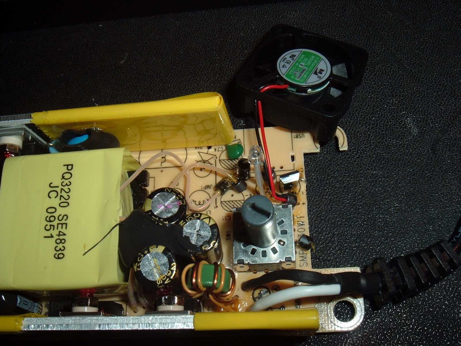
It seems to be fairly well made compared to some units I've seen. There is some unpopulated area at one end, which appears to be a 5V USB charging supply option not on this model.

Turns out the fan on there was making the noise, an 8V 30mm unit. I've removed it and tested it on a bench power supply, at 8V and it runs fine, as noisy as expected from a small fan, but not as bad as it had been inside the PSU. It seems it was being driven by a voltage which slowly rises with load, and at about 3-4V it is trying to start but fails to spin and just sits there and buzzes. Not a very good design really, it shouldn't be run below a safe guaranteed starting voltage, in this case, about 5V.

UPDATE: Comments disabled on this post as it seems to attract a lot of spam.