Showing posts with label 8032-SK. Show all posts

Sunday, 19 July 2020

Mini PET Update

This is an old post, preserved for reference.
The products and services mentioned within are no longer available.

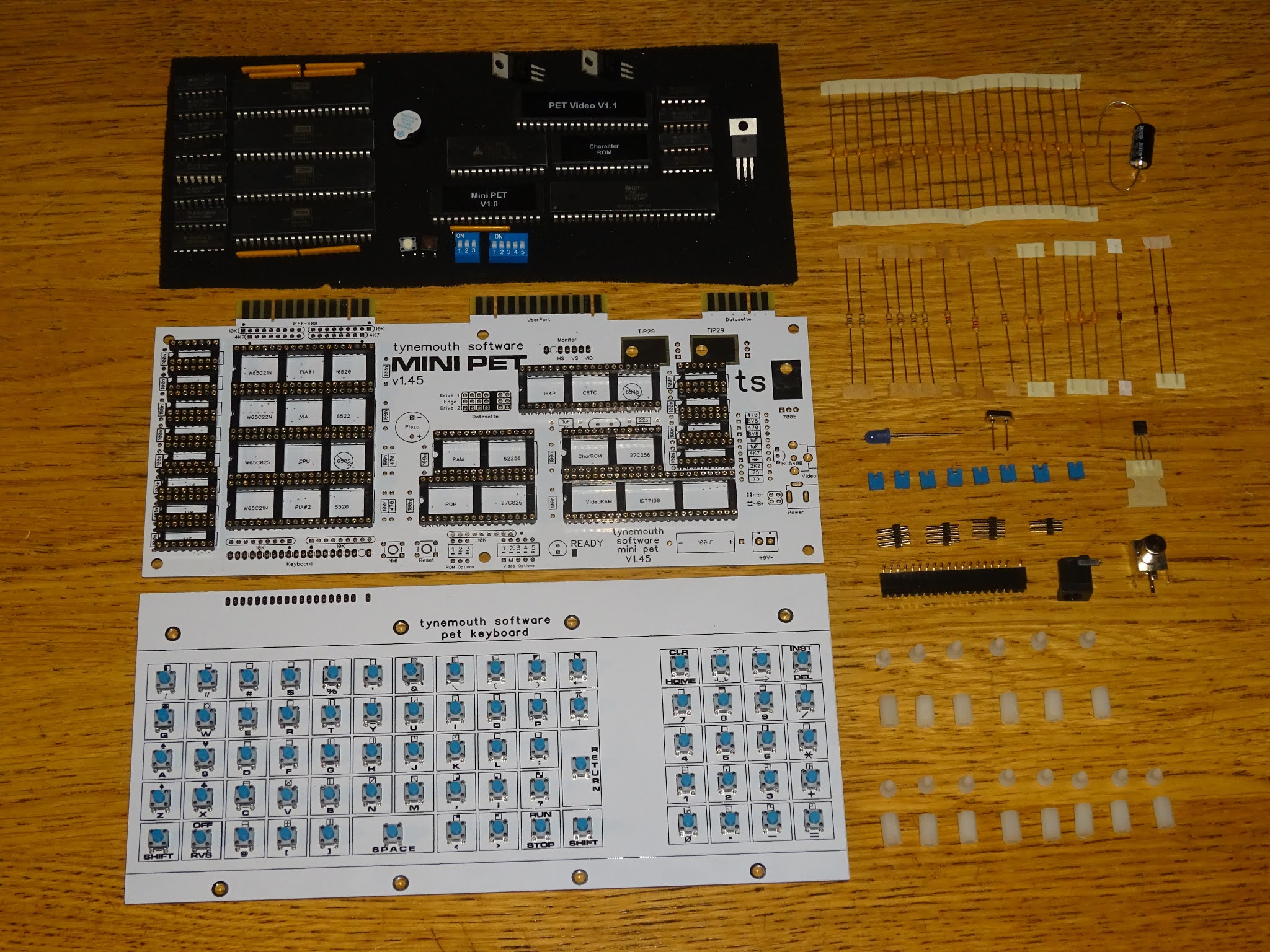
The Mini PET seems to have been received well. I am seeing lots of pictures of very neatly assembled boards (and also the one that TFW8b built) and revived PETs up and running again.
That's great to see, and very few problems building them, other than a few people who had to built it without reference to the manual (the person packing the orders has of course been fired). So far, the only issue to report is a slight error that seems to have slipped though all of our other testers (who have, of course, all now been fired).
When first putting together the design for the prototypes of the Mini PET, I came to the userport and was pleased to find I had already drawn a component for the PET userport. Perfect I thought and added it to the design. I didn't consider at the time that I had drawn that component for things which plug into the userport on a PET, not for the host side of the PET userport, which is the mirror of that pinout. (I have, of course, also been fired)
And so, the pinout is reversed. Pins that should be 1,2,3,4... are 12,11,10,9... During testing, no one it seems noticed that, as no one it seems has anything that would plug into the PET userport. The only things I had were userport sounders and composite video output. All of which were already provided on the Mini PET. I think this will only affect a handful of people making userport serial interfaces, as the PET seems to have hardly any commercial userport peripherals.
I have made some boards which reverse the pinout. An interesting routing problem, 12 wires what all need to cross over each other and the same on the other side of the board.
I'm fairly happy with the solution I came up with, although I wonder if there is a neater way to reverse the connections? Those are being sent out to anyone with an affected board (V1.42, V1.44), although no one has actually asked for one, and only one user has reported a problem. The ones going out have white soldermask.
I build a little LED tester plug to make sure that was working correctly.
Because of the userport problem, I have moved more quickly than planned to the next board designs, as correcting the pinout on the userport required quite a bit of rerouting. The updated versions of the 'Kit A' boards is V1.45.
Other than the correction to the userport pinout, and a couple of minor tweaks, this is pretty much the same as before.
The LED tester confirms the pinout on these boards is now correct, so the twister boards are not required for V1.45 and later boards. The new 'kit A' versions (for use stand alone with a keyboard) are shipping now.
The Mini PET boards had been designed to be the same size as the keyboard PCB, which had already been designed as a direct replacement for the chiclet keyboard on the 2001 PET, so the Mini PET was designed to be the same width as that.
That meant it wasn't quite wide enough to pick up on the two mounting pillars at the back of the PET case.
I had tried out a green soldermask version of the Mini PET board and that had looked better inside the PET case. It seemed a good opportunity to split this into two versions, one white soldermask board, the same size as the keyboard, for stand alone use, Kit A. The second, a green soldermask board which fits inside the PET, kit B.
The first thing to do was to make the B boards larger, so they are now the same width as the top end of the original PET boards.
So those now fit into the case and pick up on both rear mounting pillars.
It also seems a good idea to remove things not required for this version.
I've removed the DC jack, and boxed off the composite video section, which can be fitted if you need it, but otherwise can be left unpopulated.
You can see here I prefer to fit the smaller logic chips without sockets. They are still supplied in the kits if you want to use them, I just think it looks better without. TI uses the same moulding for 14 and 16 pin chips, so when aligned correctly, you don't see the difference between 14 pin and 16 pin chips.
The wider kit B boards now pick up on both rear mounting pillars, and the power supply interface board has been integrated to make a single board solution.
As before, this can be used with the 9 way power connector found in most PETs or the 5 way connector from the original 2001s. You could cut down the pin header before soldering if you are only going to be using the 5 pin connector. But it's not a problem if you don't, one missing pin is an extra ground, the other two are for a second transformer winding which is not used.  
There is now a side datasette port, for datasette 2, positioned as on later PETs, so the board gives access to both rear and side datasette ports.
This now works better for the 8032-SK case where the board is mounted at 90 degrees, and the side port becomes the rear port.
The board picks up on the same two mounting points and the extension cables connect as normal inside the 8032-SK case.
The board can alternatively be mounted further into the PET case, which allows an SD2PET to be installed inside the case. This can be useful in unattended events to keep it away from prying hands, or for those short of desk space, or wanting to access the SD card by lifting the case rather than reaching around the back.
The second datasette is still accessible through the holes in the case in this configuration.
You will see I have moved over to using jumper settings, rather than DIP switches on the B boards (thinking it would be adjusted less frequently once mounted inside a PET case). 
I'm not sure about this, and may go to a single 8 way DIP switch on future boards as it adds quite a few extra parts to be sorted out and soldered in, but keep the onboard labelling of options.
These kits are being distributed by The Future Was 8 bit. My Tindie store remains closed due to the ongoing problems with shipping. 

2022 Update: The Mini PET has been replaced by the Mini PET 40/80. This has a built in much nicer keyboard and supports 40 and 80 column mode. Also available is the Mini PET 40/80D, a preassembled drop in replacement board with a built in SD2PET. Both are available now from The Future Was 8 bit.

Wednesday, 7 October 2015

Which PETs support which PET microSD

This is an old post, preserved for reference.
The products and services mentioned within are no longer available.

This post has been left for historic information. The PET microSD is no longer in production. The replacement SD2PET is available now, more information on the pre-order page.

Not sure which PET microSD is most appropriate for your PET?

Models
PET microSD Horizontal
PET microSD Vertical
PET microSD Internal
Features
  • plugs into back
  • easy to access
  • datasette power
  • easily removable
  • sticks out a bit
  • plugs into back
  • easy to access
  • internally powered
  • no external wires
  • low profile
  • internally fitted
  • fit and forget
  • internally powered
  • no external wires
  • low profile
2001
✔(B)
✔(B)(P)
✔(B)(P)
2001N
✔
✔
✔
3032
✔
✔
✔
4032
✔
✔
✔
8032
✔
✔
✔
8096
✔
✔(P)
✔(P)
8296
✔
✔
✔(E)
8296D
✔
✔
✔
CBM-II*
✔
✘
✘
8032-SK
✘
✘
✔
8096-SK
✘
✘
✔(P)
VIC20
✔(I)
✘
✘
C64 / C128
✔(I)
✘
✘
C16 / Plus4
✔(I)(P)
✘
✘

(B) - BASIC v1.0 does not support any IEEE-488 drives, so an upgrade will be required - see below.
(P) - Alternate power connection required - let me know when ordering
(E) - The internal board would need an extension cable as capacitor C1 is in the way inside the case
(I)  - IEEE-488 adapter required - see PETmicroSD on a VIC20
 *  - Tested on CBM-II B710 and B720 with DOS 1.25 and CPM 86. Should also work on the B128 and the 600 and 700 series CBM-II machines as long as they have datasette and IEEE-488 edge connectors


If you see the BASIC 1.0 screen when you power on

*** COMMODORE BASIC *** 

and not BASIC 2.0

### COMMODORE BASIC ### 

 or BASIC 4.0

*** COMMODORE BASIC V4.0 *** 

then you need to upgrade to make use of an IEEE-488 disk drive, such as the PET microSD. The easiest way to do this is with one of my ROM/RAM boards. This is a solderless and reversible upgrade that gives selectable BASIC 1, 2 or 4 and 8K, 16K or 32K of RAM to your 2001.

UPDATE: These are current out of stock, click here to pre-oreder a PET microSD.

2022 Update: I have since designed a much nicer SD drive for a PET. The SD2PET is available from  The Future Was 8 bit

In the style of the table above, this is the compatibility of the SD2PET:

Model
SD2PET
Features
  • plugs into back
  • easy to access
  • datasette power
  • easily removable
  • sticks out a bit
2001
✔(B)
2001N
✔
3032
✔
4032
✔
8032
✔
8096
✔
8296
✔
8296D
✔
CBM-II*
✘
8032-SK
✘
8096-SK
✘
VIC20
✘
C64 / C128
✘
C16 / Plus4
✘

(B) - BASIC v1.0 does not support any IEEE-488 drives, so an upgrade will be required 
* - The 2MHz CBM II machines do not give the drive as long to reply as the 1MHz PETs, and so the SD2PET does not always respond in time. Consider these unsupported.

Tuesday, 29 September 2015

PET microSD new boards added to range

This is an old post, preserved for reference.
The products and services mentioned within are no longer available.

This post has been left for historic information. The PET microSD is no longer in production. The replacement SD2PET is available now, more information on the pre-order page.

I've been updating the design of the PET microSD, and there are now three different versions to chose from, depending on how you want to connect it, and to what machine. All of these plug into the rear edge connector of a PET from a 2001 up to an 8032 (or variations of the 8032 such as the SuperPET 9000). See later for information on 2001-8 and 8032-SK support.
OPTION 1 - PET microSD v1.2 horizontal. The two boards at the top make up the original style board, currently on V1.2. This plugs directly into the IEEE-488 port on the rear of the PET. These are still available, and still the best choice for many users.
The board needs 5V power and that is supplied from the datasette port, with a passthrough connector to attach a datasette. This means it can be moved from PET to PET and does not need the case to be opened. Just plug the boards into the back.
The V2.0 boards provide some alternative mounting arrangements, and a few changes. Firstly, since these boards aren't sticking out the back, they don't need to be as small, so I've gone back to a slightly larger boards with all the parts on the top side, so the backs of the boards now only contain the serial number and firmware version info.
Secondly, rather than tap the 5V power rail, I've added a DC-DC converter on to the board, so it can be powered from any supply from 7v to 22v. There is a handy connector, J11 on the PET board, near the back of the case. This is designed to supply unregulated 9V to add on boards, such as the 64K RAM board.
The V2.0 PET microSD boards have a short cable with a 7 pin connector. 9V is on the centre pin, so it can fit either way around to avoid any problems. If you have a board which already uses this connector, I can supply a longer lead with a clip on the end to attach to one of the reservoir capacitors.
OPTION 2 - PET microSD V2.0 vertical. The first of these new boards is a vertical version, think ZX81 RAM pack, only slightly larger capacity and no RAM pack wobble.
This plugs into the back of the PET and the power cable plugs onto J11 inside the PET (2001N onwards). It takes up very little space and allows easy access to the microSD card. This is a good choice if your PET is close to the back of the bench.
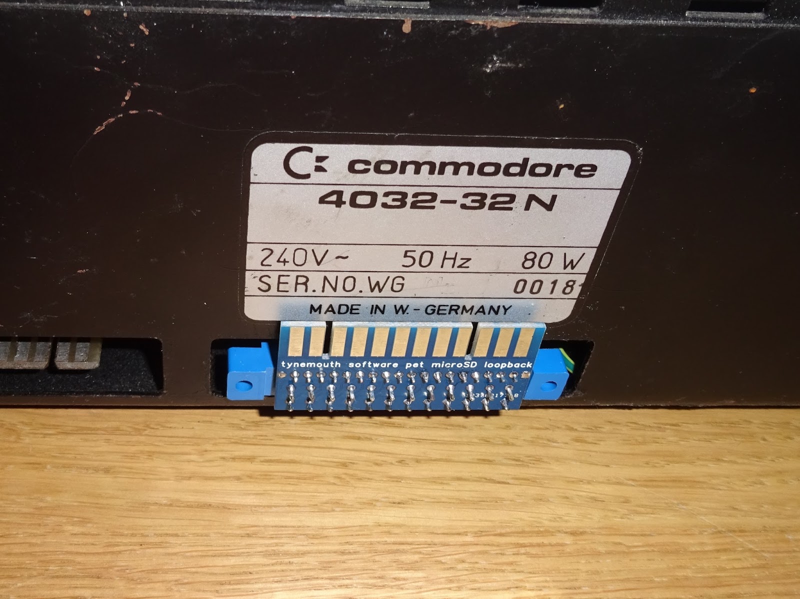
OPTION 3 - PET microSD V2.0 internal. The second new board is much requested, one that can be installed inside the PET. OK. It's not entirely internal, there is no internal IEEE-488 header on most PETs, so it has a small loopback board that plugs into the back. I'll probably remove the pass through connector in the next version of this to make it half that size.
Inside the PET, the 18 way socket on the loopback board is just visible above the connector. There is just enough space for this to fit through easily,
The PET microSD fits onto this header and also the J11 power connector as before.
This is a good option if you want it hidden out of the way and don't need to remove the microSD card very often, or are happy to open the PET to change it.
This shows the PET microSD V2.0 internal mounted onto a 4032 board outside of it's case to get an idea of how it all fits together.
The 8032-SK and 8096-SK do not have rear edge connectors, but they do have the same 8032 board, and the edge connector is internal. This board is can be used internally in an 8032-SK, with the rear panel cable now plugging into the top of the loopback board.

PET 2001
All the versions of the PET microSD can be used with the original 2001, but 2001's with BASIC 1 need to be upgraded to BASIC 2 or BASIC 4, you can use one of my ROM/RAM boards to have a configurable BASIC 1/2/4 ROM and 8/16 or 32K RAM upgrade.
The original 2001 does not have the 7 pin connector, so I would have supplied a longer lead with a clip on the end, this attaches to the 9V rail, and the easiest place is on the leg of the reverse protection diode, the furthest leg from the corner of the board.


Which one do you choose? Well choose 1 if you want to move it around between PETs or easily remove it, or don't want to open the PET case. Choose 2 or 3 if you are short of space, or prefer less wires around the back. Choose 2 if you need access to the SD card, Choose 3 if you don't plan to change the card often, or are happy to open the PET as required. Not all PETs support all options, so see the table of which PETs support which boards, which also has buy it now links.

2022 Update: I have since designed a much nicer SD drive for a PET. The SD2PET is available from  The Future Was 8 bit

Saturday, 1 August 2015

Exploding Commodore PET Mains Filters

This is an old post, preserved for reference.
The products and services mentioned within are no longer available.

You occasional find an old computer where the owner has said it blew up. Now you may think this is fanciful and related to the TV and movie attitude that computers blow up when they go wrong, or if you ask them too difficult a question. However, what they are describing is probably the mains filter capacitors failing. You get the same sort of low value capacitors filtering the mains on power supplies on computers like the BBC micro and Apple II.
Over time, these dry up and eventually crack and fill the room with acrid smoke. You can see the progression on the three caps on the bottom row, from three different BBC Micros. The left hand one looks OK, the middle is starting to crack and bulge. The right hand one fell apart whilst being removed. Had that been powered up in that state, it would have gone bang.
I now tend to replace those on BBC micros before I power them up these days, once you've had one or two do that, it's worth the effort. [UPDATE: one of these had gone bang in the ICL One Per Desk I recently repaired]
The Commodore PETs and Commodore disk drives use a separate mains filter, in a can. These too have a tendency to go bang in their old age. This is an 8250, the mains filter is the thin metal can on the side of the transformer.
Here is one that has been removed. It is marked
Funk-Enstorfilter 0.1uF + 2x2500pF XY + 2x100uH 250V ~ 2A
Or a line filter with a 0.1uF capacitor across the mains and a pair of 2500pF capacitors between live and neutral, and a pair of 100uH inductors between input and output. The purpose of these filters is reduce noise generated by the PET being fed onto the mains. This would have been a problem in its day as there were still may simple radios and televisions which did not include power supply regulation, so were sensitive to mains noise, particularly on AM radio. These days there aren't many of those in use, and there is so much noise introduced by switched mode power supplies in computers and phone chargers etc. it's hardly worth the effort.
This is an 8032-SK I'm about to start work on. You can see the red section has been partly pushed out of the can.
There is also evidence of soot on the board beneath. So this presumably exploded at some point the past. The are modern equivalents, but in this case, I am just going to remove it. The mains input goes through this device, so to remove it, it has to be bypassed.
Confusingly, the two blue wires are the inputs to the filter, and the two black wires the outputs. The four terminal blocks on the 8032-SK are normally wired as follows, starting with the nearest the back of the case.
  • black wire, neutral out of filter - blue wire, neutral to transformer
  • blue wire, mains neutral in - blue wire, neutral into filter
  • brown wire, mains live in - blue wire, live into filter
  • yellow/green, mains earth - yellow/green to earth tag

. 
The final black wire out of the filter is live out. This is soldered to the input of the fuse holder. From the fuse holder out it goes to the switch and the switched output is soldered to the wire that feeds live to the transformer. If you're doing anything with these, just take a while to follow it all thorough and don't trust the wire colours. The usual caveats about the potential side effects of death when fiddling with mains should be noted.
A quick way to do with is to remove the three wires from the filter that are screwed into the terminal blocks, and then cut the fourth wire close to the filter can. Take this wire back through the hole in the metalwork and wire it into the third terminal block (live in). The blue wire which is neutral to the transformer need to be moved down to the second terminal block (neutral in).
I prefer to do a slightly better job and desolder all the wires and redo them all in the correct colours and with a bit of heatshrink to better protect the terminals. I do this when I'm doing a full restore, removing everything, cleaning and remaining the metalwork then reassembling. This is is still do be fully cleaned up, but the wiring would be something like this.
I also desolder the transformer live wire and use the now spare screw terminal for that, so that the transformer can be more easily separated.
The 8032-SK now has power again. The monitor works (the signal coming from my 4032), but there is no video out from the main board. So a few more things to be fixed - more on those in a future post.
I normally remove these before they get a chance, but this one has already gone. Time for some investigation. Dremel powered tear down time.
The internals are fixed to the metal can, so the easiest way in was to cut the can off. Inside you can see the full horror show. The ferrite cored inductor at the top and the main capacitor in the middle.
That must have created quite a bit of smoke to push the end cap off, I'm pleased that didn't happen to me.