Yes, you read that right, ZX80 4K Integer BASIC running on a Minstrel 4D.

This is the first part in a series of posts where I will be starting with building a modified version of ZX80 BASIC and later moving on to a version of ZX81 BASIC that will run on the Minstrel 4D hardware. The final goal will be to get it running as a ZX81, and capable of running an unmodified version of 3D Monster Maze.
I will talk about the practicalities of how that works in a later post, in this post I talk about the initial idea and getting it running.
It was one of those occasions where a silly idea crept into my head and I had to give it a go.
Back in the dim and distant part, one of the original plans for the Minstrel 4th / 4D is that as well as the standard Forth, it would include other language and utility ROMs.

There are two jumpers on the 4th and two DIP switches on the Minstrel 4D to select alternate ROM images, although none were supplied as standard. The memory map of the Minstrel also has an 5K extra space available, meaning these language ROMs could be up to 13K.

I worked for quite a while on a version of Microsoft BASIC, adapted from NASOM BASIC, but I never quite got that right.
I should maybe go back and try that again, but it has been such a long time, I would probably end up starting all over again.
The main issue was the screen editor. The version of BASIC is designed to work with a serial terminal, as seen with things like the RC2014.

I tried to adapt the Ace screen editor, but that is a bit odd with the bottom one or two rows also effectively being the keyboard buffer.

I also looked at adapting the NASCOM screen editor, but that was also problematic due to the way it had a 48 column display in the middle of 64 byte screen lines.
Anyway, that didn't happen so got shelved.
....
And then, two years later, I had an idea. Hey, why not use the screen editor from the Spectrum.
But wait, why use the NASCOM BASIC, why not use the Spectrum BASIC as well.
Hey, why not make the Spectrum ROM run on the Minstrel 4th.
Well. That was last Sunday (*at the time of writing this post which went to Patreon about a month ago)
I spent a while working on the Spectrum version, but it was clear that it was going to require a lot of work to simplify the pixel based display with colour attributes to one that was character based.
Hey, what about the ZX81? That was character based, let's use that.
So I started again, but this time with the ZX81 ROM. That version is almost working, but there were some issues with slow mode that I need to rethink.
Hey, what about the ZX80? That doesn't have slow mode.
So, I started again, this time with the ZX80 4K Integer BASIC ROM.
And well, it works. There will be a full blog post explaining how I modified it to work, but for the moment, suffice to say I have it running on the Minstrel 4D.

There are various things to deal with to make it usable. The first is the keyboard, the Ace has it's bottom row of keys shifted around compared to the Sinclair machines, so I needed to adjust the key tables to cope with the new layout (for the moment, the Symbol Shift key will be the ZX80's full stop and comma key). I may look at remapping to match the symbols and maybe even a tokeniser for BASIC so you type in P R I N T rather than pressing O (yes, it was on O on the 4K BASIC, not P).

The next thing to tackle was loading. And this is where I initially got stuck. I needed to load programs to test things further, but was having no luck loading.

Hardware wise, the ZX80 and the Ace have very similar hardware for reading the keyboard and the tape. I have redrawn them in the same way, to highlight the difference. Can you spot it?

Yes, the tape input is on D5 on the Ace, rather than D7 on the Sinclair machines. D7 is handy as you can use the RLA instruction to move bit 7 into the carry flag, where it can be easily tested. In bit 5, you either have to do three RLA instructions, or use BIT 5,A to test it.
I did some clever shuffling around to make that work and keep the same number of bytes and T-states, and tried it out.
And it didn't work.
And two days later, after trying all sorts of stuff, it still doesn't work.
I am not sure why yet. It seems to be doing all the right things, but it's just not reading the bits.

Here yellow shows the reads from the port and green shows the signal from the tape. I will probably write a long blog post on this at some point on the ZX80/81 tape loading, but basically 4 pulses then a gap means a 0, 9 pulses then a gap means a 1.
This is very different from the way the Ace did it with different length pulses for 0 and 1 See an annotated listing by George Beckett:
https://github.com/markgbeckett/jupiter_ace/blob/master/mpf-i/jupiter_ace_tape_interface.asm
The full ZX80 disassembly by Geoff Wearmouth can be found here for those playing along at home:
https://web.archive.org/web/20050207050627/http://www.wearmouth.demon.co.uk/zx80.htm
You can see my modified ZX80 ROM it is sampling multiple times per pulse, as expected.

Compare that to the ZX80(ignore the slow rise on the green pulse, it is fine at a logic level, and this is the cleaned up version)

Here I have added the blue trace showing writes to RAM as each bit is read. I didn't include that on the shots of my modified version is it isn't writing to RAM, so imagine a flat blue line doing nothing.

Looking at the code, it seems that rather than counting pulses as I expected, it is actually looking for the long period without a change.

A count is started after a bit has been read, and it waits until the signal goes flat. If that is after X counts, it is a 0, if it has reached Y counts and it is a 1, anything over that is an error.
I have spent quite a while probing around at various different machines loading, but no success on the 4D with the modified ZX80 ROM.

I also tried on a Minstrel 4th, which should be pretty much the same other than it does not have the Minstrel SD cleaning up the tape signal, but that proved to be the same.

I even tried going back to the original LOAD routines and modified the hardware to use D7, in case it was my changes at fault.

Summing up where I currently am:
- Is it the signal processing on the 4D? No. Tried a Minstrel 4th.
- Is it the D5/D7 swap? No. Tried to swap it in hardware.
- Does the TZXduino produce the correct output? Yes, it loads into a Minstrel 2.
- Does the 4D board work with the Ace ROM loading from the same source? Yes.
- Are there interrupts going off during loading to affect the timing? No.
- Is it down to something else you have changed? Maybe, but I don't know what.
- Have you tried turning it off and then on again. Yes.
So I am confused. I may try to write an alternate tape loading routine, or adapt the one from the ZX81 or ZX Spectrum, but I do not understand why the original does not work.
The remainder of the BASIC seems to work as expected. Thanks to George Beckett for trying out typing in a longer BASIC test program which ran fine.

Today is Saturday, in case you needed to know.(* well, it was)

That is running in the Eighty One emulator, set to Jupiter Ace, as I can't load it yet.
Lots of things still to do, I might look at a tokeniser, and adding some extra commands, like IN and OUT, and maybe JOYSTICK to return the value read by the joystick port, and a version of the Spectrum's BEEP command. And then possibly a machine code monitor.......
Any other suggestions?
And then, I need to do all that again for the ZX81 ROM, but I think it is best to keep working on the ZX80 version for the moment as there is loads of space and the lack of slow mode just makes things easier whilst I get these things sorted.
Oh, and then I need to adapt the Minstrel SD and menu etc. so it will work with these new ROMs as well as the Ace one......
But, first I need to get the loading sorted. Spoilers, the next part is titled "Writing a new tape LOADing routine".

http://blog.tynemouthsoftware.co.uk/2023/12/zx80-basic-on-the-minstrel-4d-part-2.html
Advertisements
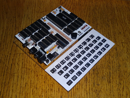
Minstrel 4D
Minstrel 4D kits and ready built units are available from thefuturewas8bit.com
https://www.thefuturewas8bit.com/shop/tynemouth-products/minstrel4d.html

Patreon
You can support me via Patreon, and get access to advance previews of blog posts and behind the scenes updates. These are often in more detail than I can fit in here. This also includes access to my Patreon only Discord server for even more regular updates.
https://www.patreon.com/tynemouthsoftware