Showing posts with label Minstrel 4D. Show all posts

Sunday, 15 September 2024

Micro Professor EPROM Programmer Board - Part 1

This was meant to be a quick post just scanning over the schematics to work out the memory map and IO connections, but you know me......

Sometime last year, I repaired a Multitech Micro-Professor MPF-I.

At the time, I remembered that I had bought some of the modules that would go with it from an electronics surplus seller called Greenweld Electronics.

Well, only a year and a bit after I sent the MPF-I back, I finally located the one remaining module.

This is an EPB-MPF-1BP (I can tell that because it says so).
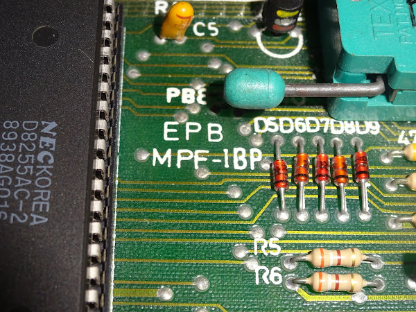
I think I bought several of these for a few pounds each when they were being sold off, probably in the early 1990s. This board was very useful for spares, but I did keep this one intact, in case I found a use for it one day.

(update: found the advert in Everyday with Practical Electronics April 1994)

And there in the middle is the Micro Professor EPROM programmer board (£3.95 + P&P)

(I think they may have reduced them further before I bought them)

Well, only 30 years later, it may finally be time to put it to use.

It was originally designed to connect to the Micro-Professor using a 40 way bus which was essentially all of the pins of the Z80. (there is a second 40 pin header to daisy chain multiple addons)

I sent the MicroProfessor back to it's owner last year, so I can't use that, but I do have several things, such as the Minstrel 4D, which have RC2014 bus connectors. That is also a 40 way bus which is essentially all the pins of the Z80.

I also know that George Beckett has been working on porting the Micro-Professor monitor to run on the Minstrel 4D, so I plan to wire this up to a Minstrel 4D, and hopefully run the original code, or if not, write some simple code myself, and finally program an EPROM after more than a quarter of a century wait.

In this first part, I am going investigate the schematics and work out what is going on. Part two will be trying to get it running.

The first page of the schematics shows the ROM, RAM and address decoding.

The board contains three 6116 2Kx8 static RAM chips and a single 2732 4Kx8 EPROM. (no I can't read what it says on the EPROM label either, but I know I put it there as that is a write protect sticker from a 5 1/4" disk)

The RAM chips are mapped as $D800-$DFFF, $E000-$E7FF and $E800-$EFFF, giving 6K from $D800-$EFFF. Combined with the standard 2K of RAM on the Micro-Professor at $F000-$F7FF, this gives a contiguous 8K block of RAM to use to store data ready to write to an EPROM.

Looking at the schematic, I was slightly confused by the connections to the 74LS138 at U10. It appears as though /RD is used as one of the gate inputs, which would make the RAM read only?

It would seem more likely that it should be /MREQ on that pin, so the RAM was only selected for memory accesses.

Probing the board confirms this, U10 pin 4 is in fact connected to /MREQ and not /RD. So, I will have to remember to not necessarily trust these schematics.

(update, I went back and checked the schematics in the scanned version of the manual, these were drawn differently, but also include the same error)

Although the extra 6K of RAM would have been very useful on the Micro-Professor, I will probably remove it when using it with the Minstrel 4D, as that already has a full compliment of RAM.

The 4K ROM is mapped to addresses $9000-$9FFF, and includes software for both versions of the Micro-Professor, the MPF-I (with 6 seven segments LEDs) and the later MPF-I-Plus with the alphanumeric LCD). As with the RAM, I will need to remove this and load the contents into RAM. That's fine as it will probably need various modifications anyway.

Also on this page is the decoding for the IO chips.

This generates two signals, one for an 8 bit latch clock and one for the chip select of the 8255 IO chip.

The three gate inputs are wired so that the chip is active when A6 is high, A7 is low and there is an IO request.

That means it covers the address range 01xx xxx, (0100 0000 through to 0111 1111), $40 through to $7F.

This is split into 8 blocks, each of which activate one of the 8 outputs Y0-Y7. These are controlled by A3, A4 and A5, so the blocks will be $40-$47, $48-$4F, $50-$57 etc. The last two will be $70-$77 and $78-$7F, and those are the ones that are used here to drive the IO chips on the next page of the schematics.

The latch will be activated by any address from $70 through to $77, and the 8255 any address from $78-$7F.

There are four registers in the 8255, and it's address lines have been wired to A0 and A1. No additional address lines are used with the latch, so it will cover the whole of it's address allocation.

Address
Register
Connected to
$70 (or $71-77)
273 Latch
EPROM VPP/OE/CS
$78 (or $7C)
8255 Port A
EPROM D0-D7
$79 (or $7D)
8255 Port B
EPROM A0-A7
$7A (or $7E)
8255 Port C
EPROM A8-A10
$7B (or $7F)
8255 Control
-

Various types of obsolete EPROM are supported, either 24 or 28 pin. Note the genuine (?) TEXTOOL socket (not TEXTDOL as seen on ebay fakes), complete with helpful annotation from a teenage me.

It might actually be useful for programming the slightly odd chips like the 2532 and 2564 that can be used to replace mask ROMs on Commodore machines.

The 74LS273 latch controls pins on the EPROM that require different voltage levels. VPP can be 0V, 5V or something up to 25V (modern EPROMs are more likely to use 12V, but EPROMs of this vintage needed a higher voltage). Sometimes this is mixed with the OE and/or CS pins to make room for more address lines on the EPROMs.

Each of the outputs drives one gate of 74LS06 open collector inverter. When it's input is low, it is effectively not there. When the input is high, the output is pulled low.

If I understand this correctly, when the value in the latch is all zeros (after reset), EPROM pins 1, 22 and 23 will be at 5V. If any of the bits are set to 1, then the voltages will change as follows:

Bit
Pin
Voltage
Q0
Pin 1
VPP
Q1
Pin 1
0V
Q2
Pin 22
VPP
Q3
Pin 22
0V
Q4
Pin 23
VPP
Q5
Pin 23
0V

So, obviously, don't set both bits for any pin at the same time or the 10Ω resistors and transistors will get warm.

Bit Q6 and Q7 are not used. I would have been tempted to wire those to LEDs to maybe one to show reading the EPROM and one to show writing?

The final element is the VPP generator. This is based on a TL497 switching regulator. Probably programmed for about 25V, with the option to include 5 diodes in series with the output, bringing it down by about 3V to 22V (ideally 25V and 21.5V).

Hmm, that doesn't look right. Resistors R3, R2 and R1 form a potential divider, which should make pin 1 1.2V when the correct voltage is reached. They are all shown as 15K, which would mean the target voltage was 3.6V?

Ah, no, it's meant to be 1.5K, that makes more sense (although the datasheets all seem to specify 1.2K).

That makes the voltage divider more reasonable, giving a target around 25.2V.

Another correction to the schematics.

Note to self, adding a second switch to short out one of the 15K resistors would bring the target voltage down to 13.2V which is probably close enough for modern 12.5V EPROMs.

I should also mention in passing that there was also an earlier version, the EPB-MPF. This had only a 24 pin EPROM socket, 4K of RAM and 2K of ROM, and there are a lot of difference to the implementation.

What is next? Well, I have read out the EPROM on there, and it does contain apparently valid code, which George has started looking into to see how painlessly it can be made to run on the Minstrel 4D.

Now I know how it is wired up, next time I will have a go at driving it.

In future, it might be interesting to see if this can be turned into a viable EPROM programmer with the addition of an RC2014 serial card, data could be read, edited, written etc. using the Minstrel 4D interface.


Advertisements

Minstrel 4D

The Minstrel 4D is a much more reliable and usable Jupiter Ace compatible computer, with all the extras like a joystick interface, SD card loader, RC2014 expansion bus etc. Available in kit and built form from The Future Was 8 bit.

More info in a previous post:


RC2014 Serial Card

My version of an RC2014 serial card is available from Z80kits.com, and is an ideal companion to the Minstrel 4D


Patreon

You can support me via Patreon, and get access to advance previews of posts like this and behind the scenes updates. These are often in more detail than I can fit in here, and Patreon is currently getting a lot development logs on a new project at the moment. This also includes access to my Patreon only Discord server for even more regular updates.

https://www.patreon.com/tynemouthsoftware

Sunday, 17 December 2023

ZX80 BASIC on a Minstrel 4D - Part 4 - ZX80 Autoload

I have been working on porting ZX80 BASIC to the Minstrel 4D. Hardware that was designed to run the Jupiter Ace, without making any hardware changes.

The next target for things to get working were two excellent flicker-free ZX80 games from Paul Farrow.

Following on from the post testing games on the ZX80 BASIC port on the Minstrel 4D, I had got as far as testing Paul's ZX80 version of Mazogs - http://www.fruitcake.plus.com/Sinclair/ZX80/FlickerFree/ZX80_Mazogs.htm

I was pleased to see that working well.

But when I tested ZX80 Kong, that unfortunately did not work, just giving an odd single line listing. - http://www.fruitcake.plus.com/Sinclair/ZX80/FlickerFree/ZX80_Kong.htm

ZX80 Pacman was the same.

I wasn't sure what was going on here, other flicker-free mechanisms did appear to be working, so why were these games not running?

I remembered that unusually for the ZX80 these games ran directly after loading, rather than needing RUN or GOTO 100 etc. to be typed.

The page includes the following lines:

The game is written entirely in machine code, and uses the technique developed by Martin Knorth to auto-run upon loading. It first performs an integrity test to ensure that it has loaded from cassette correctly and should an error be detected then a return to BASIC is made and an error message displayed.

I contacted Paul and asked if he could tell me more, to see if that was indeed the problem, and he kindly replied with the information and link to the appropraite page.

I added a quick bodge to test the theory, and it worked first time.

First the "Lightening Software" logo page, and then the Kong title screen.

That all appeared to be working, so time to try the game.

And yes, it works fine. There are a couple of caveats. The game appeared to be running slow, but I think that was just the inefficient bodge to test proof of principle. It should hopefully run at the correct speed once that has been implemented better. (it did)

The keys default to the arrow keys. Left and Right are the same, but up and down are reversed between the ZX80 and Jupiter Ace, so you need to press the 7 key, marked down, to move up.

There quite a lot of other control options, unfortunately (although fully justifiably), it does not include support for the Boldfield joystick port on the Minstrel 4D. There are other keyboard options, including QA OP + M and others. However, to get to these you have to press the C key. The keyboard scanning routine has been replaced, so it has the same problem as Hampton's maze, the keys on the bottom row are offset one place, so you have to press X rather than C.

Most programs use the ROM keyboard scan routines, which have been adjusted for the Minstrel 4D keyboard layout, but anything with it's own scan routines is going to have this issue.

ZX80 Pacman also worked -http://www.fruitcake.plus.com/Sinclair/ZX80/FlickerFree/ZX80_Pacman.htm

This had the same issues with the keyboard scanning on the bottom row of keys, but otherwise played great.

It is interesting to note there is no clicking in the flicker-free routines used in these games, I think they are using OUT $FF,A rather than the OUT $FE,A that was triggering the clicking.

How does the autostart work?

So, what had caused them not to work? Well, a clue can be gleaned from the loading screen I was seeing with line one with just a black square.

The technique used was devised by Martin Korth, and is the "nocash LD H,L trick".

See https://problemkaputt.de/zxdocs.htm#zx80zx81cassettefilecontent

Remember from "How the ZX80 Generates Video" that the screen information in the display file is executed as it is stepped through. If address bit 15 is set, the ZX80 hardware is in screen drawing mode. 

http://blog.tynemouthsoftware.co.uk/2023/10/how-the-zx80-generates-video.html

When the ZX80 hardware sees an execute cycle, data bit 6 is used to see if this is a printable character. If it is one of $00-3F (normal characters) or $80-$BF (inverse characters), then bit 6 is not set. The hardware detects this and the Z80 is sent a NOP instruction to execute instead. When bit 6 is set, the value from the display file is executed. The normal use for this is $76 the newline character which is also the opcode for "Halt".

The special listing seen above is constructed such that line one contains a value which does have bit 6 set, and so is executed as the screen is being drawn.

This is $65, LOAD H,L

The HL register pair is used to store a pointer to the display file, with address bit 15 set, so it is treated specially by the hardware. The is the display file mirror in upper RAM, in the $C000-$FFFF region.

The position is directly after the program in memory, so it varies with the program size.

The technique requires the program size to be padded out so it ends at a point where the lower byte of the address is $3D.

Say the program ends at $503D. The display file will start at $503E, and to generate the display bit 15 of the address is set to make this $D03E. The code jumps to that address is set and the Z80 will start to "execute" the display file. The hardware detects bit 15 has been set and starts to draw the display (the sync pulse will have already been generated).

When it hits the $65, HL will be holding $D040. HL is a 16 bit pair made from registers H and L, with H holding $D0 and L holding $40. The LD H, L instruction will load $40 in H, making HL $4040.

When it gets to the next display line, it will be expecting to jump back into the display file using the HL pointer, but instead will jump to $4040. This address does not have bit 15 set, so will not be interpreted as display data and instead will be executed as normal code.

$4040 will be the entry point into the user program, so it will start to execute. Neat.

Making that work on the Minstrel 4D

This was not working on the Minstrel 4D as the display hardware is very different, so does not execute the display file in the same way, so the LD command was not being executed and the program was not starting.

My initial hack to get this working was to check each character as it was being drawn to the screen, and when it hit a $65, it would jump to $4040 and execute the code there.

You can that in this photo taken at just the right time. (I had to do that twice as I had to take all these pictures again. Apparently my camera will happily take pictures, make the noise, show the preview etc. all with no SD card installed. Ask me how I know.) 

Loading is complete, and the listing has started, but as soon as the $65 was going to be written, it instead jumped to $4040, which is executing some code before it finally clears the screen and starts the game.

That was not ideal as that meant an extra delay on each character to test against $65 and then $76 (halt / newline). Instead I modified the LOAD completion routine. It only runs after the load is compelte, and checks for the presence of the specially crafted trick line. If it detects that, it jumps to $4040 instead of jumping to the routine which will list the program as normal on LOAD completion.

This returned the game to normal speed and it went neatly from the end of loading to the game splash screen.


Trying out the autoloader

I thought it might be interesting to try out this autoload mechanism.

I was looking around for some simple test program I could make autostart, when I thought that I could use the Macronics games I had previously tested.

Those were small ZX80 games that were published as type in listings as well as sold on tape, so were quite small. I was already looking at generating versions patched to use OUT $FF,A like the ZX80 ROM does, rather than OUT $FE,A that Macronics used and unfortunately causes the speaker to tick on the Minstrel 4D.

There are disassemblies and details analysis of these games on Paul Farrow's site:

I started with the disassembly, planning to rebase the code to start at $4040, to fit in with the autostart mechanism. I think that would have worked with the 3K game, but things were too tight for the two 1K games.

It's easy to forget the screen display on a ZX80 is 32x24, so 768 bytes, and the unexpanded machine has only 1024 bytes of RAM. That leaves only 256 bytes for the code, stack, variables etc. This is why the 1K version of space invaders uses a partial screen as there is not enough RAM to make it full size.

(hard to believe you can have a playable game in just 256 bytes when you think of modern games where even the update patches can be several gigabytes).

The original programs used a BASIC loader. The code was present in hex values in PRINT statements. This was extracted and copies to RAM at $4000 (the base of ZX80 RAM) and executed. In the process, this overwrote the original PRINT statements, but the extracted code was smaller than the container, so no problem there.

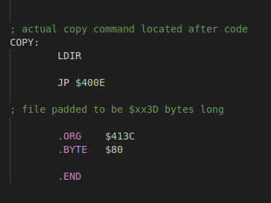
I decided the easiest approach was to do something similar. I wrote a loader program with the appropriate autostart header. This will jump to $4040 after loading, so at $4040 I jump to a simple routine at the end of the file to copy the code into place and then jump to the entry point in the game, the same as the BASIC loader did.

With a couple of caveats, that worked perfectly.

The first caveat is one I forgot at first, when executing jumps to $4040, it is actually in the process of drawing the screen, so interrupts are enabled, and interrupt is wired directly to the A6 line. When code execution reaches a point where A6 is low (e.g. $4060), it will fire an interrupt and jump to whatever you currently have in the HL register, which is probably not what you want. So the first instruction has to be DI to disable interrupts until you are ready to start drawing the screen.

The second is the file has to be a specific size, $xx3D bytes. The way I first tried this out with breakout, I was hoping it would be $413D, but unfortunately the code for copying just knocked it over by one byte and it would have needed to be $423D bytes long with 254 zeroes padding it at the end.

That was not ideal, but there was some padding before $4040, so I move the setup code there. I still had to jump to the end of the file but only for the LDIR and JP instructions to activate the copy and jump to the entry point.

I have created autostart versions of Breakout, and the 1K and 3K versions of Space Invaders. These will autostart on loading, and include the patch to use OUT $FF,A.

https://github.com/tynemouthsoftware/ZX80-4K

I have put those on my github if anyone is interested. They also work on a real ZX80 or Minstrel 2 with the original ZX80 4K integer BASIC ROM.


Advertisements

Minstrel 2

Minstrel 2 kits and ready built units are available from my SellMyRetro store.

http://blog.tynemouthsoftware.co.uk/2023/09/minstrel-and-mini-pet-kit-updates.html

Minstrel 4D

Minstrel 4D kits and ready built units are available from thefuturewas8bit.com

https://www.thefuturewas8bit.com/shop/tynemouth-products/minstrel4d.html


Patreon

You can support me via Patreon, and get access to advance previews of blog posts and behind the scenes updates. These are often in more detail than I can fit in here. This also includes access to my Patreon only Discord server for even more regular updates.

https://www.patreon.com/tynemouthsoftware

Sunday, 10 December 2023

ZX80 BASIC on a Minstrel 4D - Part 3 - Testing some flicker-free games

Continuing the series of posts from Patreon in November, working on getting ZX80 BASIC running on the Minstrel 4D. This one reworked from several posts. I have since updated this to also include a section about the updates to the LOAD routines.

In the previous post I got ZX80 BASIC running on the Minstrel 4D, and with the help of new LOAD and SAVE routines was able to load ZX80 games.

This is a modified ZX80 ROM running on Minstrel 4D hardware which was designed to run the Jupiter Ace ROM.

I had tried lots of programs which used the normal ZX80 display mechanism, including board games and text adventures etc. Games that suit the display - think - display type mechanism the ZX80 used.

Due to the way the screen is displayed on the ZX80, it was not possible to do the sort of fast moving shoot-em-up style games, at least not in BASIC.

I wanted to see some space invaders, and luckily back in the day some ingenious methods were found to make that happen.

Flicker-free games

All of the games I had tested up to this point used the display in the standard ZX80 way. There would normally be a screen flicker when the AI player was making there move, but here the screen remains static until it is next updated.

I am hoping that the many "flicker-free" games for the ZX80 will be usable

The idea in brief is to bypass part of the display routines in ROM, and then run short blocks of precisely timed code in the gaps at the top and bottom of the screen, returning to the ROM code to do the actual screen drawing.

Each of the blocks of code needs to take exactly the same number of cycles, so you have to be very careful with anything that is conditional (did the player fire, does that alien need to move down a row etc.) so that all paths through the code take the same number of cycles.

I will link for reference Paul Farrow and George Beckett's work on this subject:

http://www.fruitcake.plus.com/Sinclair/ZX80/FlickerFree/ZX80_DisplayMechanism.htm

https://github.com/markgbeckett/zx80/tree/main/hampsons_plane

The first one I tried was a simple demo from the article that first introduced this concept.

That was unfortunately the only one that worked at that point.

I did some more research and a bit of debugging, and was able to tweak the way my new display routines generated the display to fit with the expectations of the flicker-free games.

Breakout

I started with probably the earlier games, those from Macronics (http://www.fruitcake.plus.com/Sinclair/ZX80/SoftwareArchive4K/Macronics.htm)

Breakout is working well, with a small caveat. It takes over some of the display drawing, and includes turning on and off the VSync generator. Yes, the same one that now drives the speaker. Yes it now makes a ticking sound.

The code use IN FE and OUT FE instructions to turn on and off the sync generator. The actual values used are not important on the ZX80. The IN is only decoded as IO READ where A0=0, i.e. any even address would do. The OUT is only decoded as IO WRITE, so any address could be used. FF seems the best option, that is what is used in the ZX80 ROM. FD is used on the ZX81 to control the NMI generator (decoded as A1=0), so FF is safe as it will not trigger either of those.

See http://blog.tynemouthsoftware.co.uk/2023/10/how-the-zx80-generates-video.html for more details.

They published breakout as a type in listing. Yes, that is the entire game. The highlighted D3 FE is the relevant instruction, changing that to D3 FF will stop the clicking sound and will still work on the ZX80 and the Minstrel 4D.

George Beckett generated a patched version, and that works nicely. It is not ideal, but patching the games or modifying the hardware are the only options here. There are only a few games like this, so we can provide patched versions of any of those which use OUT FE.

Space Invaders

Macronics released two versions of Space Invaders (or Space Intruders), a full screen one for 3K RAM which works fine.

They also produced a version which runs on an unexpanded 1K machine. To make that fit, they reduced the number of rows on the screen. Trying that version on the Minstrel 4D, the game is playing correctly, but the remnants of the BASIC program are still visible in the part of the screen that is not being updated. (note this is one of those games where you need to type GO TO 100 to start it rather than run)

I adjusted my display routine to pad out the rest with spaces, so that now works fine.

I could centre it vertically based on the number of rows being drawn, but as far as I know it is only this one game, and is how it would have looked on the ZX80, so I will just leave it for the moment.

Hampson's Plane

George Beckett has produced a flicker-free implementation of Hampson's Plane for the ZX80.

https://github.com/markgbeckett/zx80/tree/main/hampsons_plane

It didn't initially work, but that turned out to be it not detecting that a key had been pressed. The actual display side was fine it was just waiting for the user the enter the skill level.

The keyboard differences will be an issue for a few games that implement their own keyboard routine, reading a byte from the keyboard port and then doing a comparison without masking off bits.

On the ZX80, bits 0-4 are defined for the keyboard columns. The other three are not relevant to the keyboard. Bit 7 is the tape input, and will normally be low. Bit 6 is pulled high on UK systems, but will read low on USA systems, and bit 5 is undefined so may read high or low.

On the Ace, the same bits 0-4 are defined for the keyboard. Bit 5 is the tape input, again normally low. Bits 6 and 7 are undefined but will float high on the Minstrel 4D. (see a previous blog post about the issues a similar problem caused with type 2 interrupts on the game Valkyr).

I suggested rotating a bit at a time into carry and testing that, which also worked out a bit more efficient and is consistent timing.

However, there is another issue because it has it's own keyboard scanning routine rather than the ROM one, it will misread the bottom row (see the previous post)

It would be possible to produce special builds for the 4D or possibly one that detects the system. There are various ways that could be done.

  • Read of port FE, bit 7 will be high on the 4D, but is the tape on the ZX80, so will read low.
  • Alternatively, and probably more reliably, pick a byte in ROM that is going to be different. The first byte in the ZX80 ROM is 21. But the new 4D version is C3, so just read 0000 to tell.
  • Or maybe a more subversive method would be to add "Press C to continue" on the first screen, and then seeing if that reads as C (ZX80) or V (Minstrel 4D).

George implemented the changes (with Press C to start) and also switched to using OUT FF to get rid of the background hum and it is now running well on both the ZX80 and the Minstrel 4D.

Mazogs

Paul Farrow has adapted Mazogs to run on the ZX80 with flicker-free display.

http://www.fruitcake.plus.com/Sinclair/ZX80/FlickerFree/ZX80_Mazogs.htm

I was pleased to see that ran well. It also ran without the clicking sound, I believe it uses OUT FF instructions, so does not trigger the speaker in the Minstrel 4D.

But unfortunately his versions of Kong and Pacman do not. I think this is something to do with the autostart rather than the flicker free, but I will investigate further. (they are now working, but that is a whole blog post of it's own - coming next week).

This is all I get when they load?

LOAD routine updates

The new LOAD and SAVE routines I wrote were covered in the previous post. I added a status box, which showed the address currently being loaded. This started at 4000 and went up to the end of the file.

I was thinking as I was testing these files that it would be nice if there was an actual progress bar.

It should be possible as the file size is known. That is the way LOAD knows to stop, when it gets to the end address.

The calculations involved to scale this would be a little complicated and probably too much work. I started looking at showing a bar that simply ran from 4000-7FFF, the standard 16K RAM. Only the largest programs would get to the end of the bar, so that may be interesting, but is probably not much use.

Instead I decided an easy alternative was to switch to showing bytes remaining. The user then sees a countdown of the number of bytes still to be loaded, so you can watch it could down to 0000 when it will have loaded.

It will actually start with the wrong number at first, due to the way the ZX80 works. There is a sort of file header which is actually just the RAM from 4000 upwards. This starts with system variables and includes at 400A the address of the end of the program. At the start of load, the value of the high byte is incremented, so it should be at least long enough to get passed the point where the values at 400A have been overwritten by the value stored on the tape, which is the actual end address. After that point, the displayed value will be correct.

SAVE has also been similarly updated, so a countdown to 0000 as it is saving.

Results

With the exceptions of the Kong and Pacman, all the games I have tried have worked.

There are a few games that I know will not work. The Metropolis demo (which I believe was developed on a Minstrel 2) uses a complete replacement display routine, so that will not work with this hardware. The same is true of the two Beam Software games (Super Invasion and Double Breakout) and QS Defender, as they also replace the entire display routine.

I think pretty much any other ZX80 software will just work, but there are a couple of caveats.

Anything in BASIC should be fine, and even machine code as long as it calls the ROM routines for reading the keyboard reading, load and save and video generation, everything is fine.

If any code has it's own keyboard routines, then the bottom row of keys will read wrong.

If any code has it's own keyboard routines, and does not mask off the unused bits, it may not read correctly depending on the method of testing the keys.

If any code has it's own load routine, they will fail as the tape signal is read from a different pin.

Flicker-free games will work as long as they do not replace the entire display routine.

Any flicker-free games that use OUT FE,A in the display routine will cause the speaker click. Any that do as the ZX80 ROM does and use OUT FF,A (or can be patched to do so) will be fine.


In the next post I will go into details of why Kong and Pacman were not working, and what was required to get them running.

http://blog.tynemouthsoftware.co.uk/2023/12/zx80-basic-on-the-minstrel-4d-part-4.html


Advertisements

Minstrel 4D

Minstrel 4D kits and ready built units are available from thefuturewas8bit.com

https://www.thefuturewas8bit.com/shop/tynemouth-products/minstrel4d.html


Patreon

You can support me via Patreon, and get access to advance previews of blog posts and behind the scenes updates. These are often in more detail than I can fit in here. This also includes access to my Patreon only Discord server for even more regular updates.

https://www.patreon.com/tynemouthsoftware