
This was meant to be a quick post just scanning over the schematics to work out the memory map and IO connections, but you know me......
Sometime last year, I repaired a Multitech Micro-Professor MPF-I.
At the time, I remembered that I had bought some of the modules that would go with it from an electronics surplus seller called Greenweld Electronics.
Well, only a year and a bit after I sent the MPF-I back, I finally located the one remaining module.

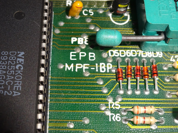
This is an EPB-MPF-1BP (I can tell that because it says so).
I think I bought several of these for a few pounds each when they were being sold off, probably in the early 1990s. This board was very useful for spares, but I did keep this one intact, in case I found a use for it one day.
(update: found the advert in Everyday with Practical Electronics April 1994)

And there in the middle is the Micro Professor EPROM programmer board (£3.95 + P&P)

(I think they may have reduced them further before I bought them)
Well, only 30 years later, it may finally be time to put it to use.
It was originally designed to connect to the Micro-Professor using a 40 way bus which was essentially all of the pins of the Z80. (there is a second 40 pin header to daisy chain multiple addons)

I sent the MicroProfessor back to it's owner last year, so I can't use that, but I do have several things, such as the Minstrel 4D, which have RC2014 bus connectors. That is also a 40 way bus which is essentially all the pins of the Z80.

I also know that George Beckett has been working on porting the Micro-Professor monitor to run on the Minstrel 4D, so I plan to wire this up to a Minstrel 4D, and hopefully run the original code, or if not, write some simple code myself, and finally program an EPROM after more than a quarter of a century wait.
In this first part, I am going investigate the schematics and work out what is going on. Part two will be trying to get it running.
The first page of the schematics shows the ROM, RAM and address decoding.

The board contains three 6116 2Kx8 static RAM chips and a single 2732 4Kx8 EPROM. (no I can't read what it says on the EPROM label either, but I know I put it there as that is a write protect sticker from a 5 1/4" disk)

The RAM chips are mapped as $D800-$DFFF, $E000-$E7FF and $E800-$EFFF, giving 6K from $D800-$EFFF. Combined with the standard 2K of RAM on the Micro-Professor at $F000-$F7FF, this gives a contiguous 8K block of RAM to use to store data ready to write to an EPROM.
Looking at the schematic, I was slightly confused by the connections to the 74LS138 at U10. It appears as though /RD is used as one of the gate inputs, which would make the RAM read only?

It would seem more likely that it should be /MREQ on that pin, so the RAM was only selected for memory accesses.
Probing the board confirms this, U10 pin 4 is in fact connected to /MREQ and not /RD. So, I will have to remember to not necessarily trust these schematics.

(update, I went back and checked the schematics in the scanned version of the manual, these were drawn differently, but also include the same error)

Although the extra 6K of RAM would have been very useful on the Micro-Professor, I will probably remove it when using it with the Minstrel 4D, as that already has a full compliment of RAM.

The 4K ROM is mapped to addresses $9000-$9FFF, and includes software for both versions of the Micro-Professor, the MPF-I (with 6 seven segments LEDs) and the later MPF-I-Plus with the alphanumeric LCD). As with the RAM, I will need to remove this and load the contents into RAM. That's fine as it will probably need various modifications anyway.
Also on this page is the decoding for the IO chips.

This generates two signals, one for an 8 bit latch clock and one for the chip select of the 8255 IO chip.
The three gate inputs are wired so that the chip is active when A6 is high, A7 is low and there is an IO request.
That means it covers the address range 01xx xxx, (0100 0000 through to 0111 1111), $40 through to $7F.
This is split into 8 blocks, each of which activate one of the 8 outputs Y0-Y7. These are controlled by A3, A4 and A5, so the blocks will be $40-$47, $48-$4F, $50-$57 etc. The last two will be $70-$77 and $78-$7F, and those are the ones that are used here to drive the IO chips on the next page of the schematics.

The latch will be activated by any address from $70 through to $77, and the 8255 any address from $78-$7F.

There are four registers in the 8255, and it's address lines have been wired to A0 and A1. No additional address lines are used with the latch, so it will cover the whole of it's address allocation.
Address |
Register |
Connected to |
|---|---|---|
$70 (or $71-77) |
273 Latch |
EPROM VPP/OE/CS |
$78 (or $7C) |
8255 Port A |
EPROM D0-D7 |
$79 (or $7D) |
8255 Port B |
EPROM A0-A7 |
$7A (or $7E) |
8255 Port C |
EPROM A8-A10 |
$7B (or $7F) |
8255 Control |
- |
Various types of obsolete EPROM are supported, either 24 or 28 pin. Note the genuine (?) TEXTOOL socket (not TEXTDOL as seen on ebay fakes), complete with helpful annotation from a teenage me.

It might actually be useful for programming the slightly odd chips like the 2532 and 2564 that can be used to replace mask ROMs on Commodore machines.

The 74LS273 latch controls pins on the EPROM that require different voltage levels. VPP can be 0V, 5V or something up to 25V (modern EPROMs are more likely to use 12V, but EPROMs of this vintage needed a higher voltage). Sometimes this is mixed with the OE and/or CS pins to make room for more address lines on the EPROMs.

Each of the outputs drives one gate of 74LS06 open collector inverter. When it's input is low, it is effectively not there. When the input is high, the output is pulled low.

If I understand this correctly, when the value in the latch is all zeros (after reset), EPROM pins 1, 22 and 23 will be at 5V. If any of the bits are set to 1, then the voltages will change as follows:
Bit |
Pin |
Voltage |
|---|---|---|
Q0 |
Pin 1 |
VPP |
Q1 |
Pin 1 |
0V |
Q2 |
Pin 22 |
VPP |
Q3 |
Pin 22 |
0V |
Q4 |
Pin 23 |
VPP |
Q5 |
Pin 23 |
0V |
So, obviously, don't set both bits for any pin at the same time or the 10Ω resistors and transistors will get warm.
Bit Q6 and Q7 are not used. I would have been tempted to wire those to LEDs to maybe one to show reading the EPROM and one to show writing?
The final element is the VPP generator. This is based on a TL497 switching regulator. Probably programmed for about 25V, with the option to include 5 diodes in series with the output, bringing it down by about 3V to 22V (ideally 25V and 21.5V).

Hmm, that doesn't look right. Resistors R3, R2 and R1 form a potential divider, which should make pin 1 1.2V when the correct voltage is reached. They are all shown as 15K, which would mean the target voltage was 3.6V?

Ah, no, it's meant to be 1.5K, that makes more sense (although the datasheets all seem to specify 1.2K).
That makes the voltage divider more reasonable, giving a target around 25.2V.
Another correction to the schematics.

Note to self, adding a second switch to short out one of the 15K resistors would bring the target voltage down to 13.2V which is probably close enough for modern 12.5V EPROMs.
I should also mention in passing that there was also an earlier version, the EPB-MPF. This had only a 24 pin EPROM socket, 4K of RAM and 2K of ROM, and there are a lot of difference to the implementation.

What is next? Well, I have read out the EPROM on there, and it does contain apparently valid code, which George has started looking into to see how painlessly it can be made to run on the Minstrel 4D.
Now I know how it is wired up, next time I will have a go at driving it.
In future, it might be interesting to see if this can be turned into a viable EPROM programmer with the addition of an RC2014 serial card, data could be read, edited, written etc. using the Minstrel 4D interface.
Advertisements
Minstrel 4D
The Minstrel 4D is a much more reliable and usable Jupiter Ace compatible computer, with all the extras like a joystick interface, SD card loader, RC2014 expansion bus etc. Available in kit and built form from The Future Was 8 bit.
More info in a previous post:

RC2014 Serial Card
My version of an RC2014 serial card is available from Z80kits.com, and is an ideal companion to the Minstrel 4D

Patreon
You can support me via Patreon, and get access to advance previews of posts like this and behind the scenes updates. These are often in more detail than I can fit in here, and Patreon is currently getting a lot development logs on a new project at the moment. This also includes access to my Patreon only Discord server for even more regular updates.
https://www.patreon.com/tynemouthsoftware
