
A couple of months ago, I built a PET serial interface (blog post to follow), and was talking to TFW8b about it. They revealed a secret plan they had been working on was along similar lines. A scheme that would later be called ..... Jelly Load.

The idea was to inject data into videos on the TFW8b YouTube channel in the form of flashing symbols in the corner of the video. "wouldn't it be cool if you could download the game I was playing whilst you were watching the video, and then play it yourself?"

Initial suggestions were flashing eyes of the real Rod Hull, of the lights on the pictures of the SD2IEC, divMMC or Kung Flu Flash.
I had to dash TFW8b's dreams by application of mathematics. It's not certain what frame rate we would be looking at, somewhere between 24 and 60 frames per second, depending on what post-processing YouTube does to the videos - let's leave worrying about that until later.
Let's take the best option, 60 individual valid frames of video. If you could sync up the receiving machine (let's leave worrying about that until later) exactly to sample those 60 frames and there was no buffering, adverts, mouse pointers moved across the screens, screen savers, screen dimming, windows updates etc. (let's leave worrying about those until later).
Let's also assume you have a very precise receiver that is able to pinpoint when Rod's eye's go red and turn that into a clean serial bitstream of 0's and 1's (let's leave worrying about that until later).
Assuming all that is perfect, you would get 60 bits per second. With a bit of formatting for RS232, that means you would 6 bytes per second. Say you wanted to transmit a 32K program, that would take about 90 minutes.
That was the best case, worse case would be many times that, depending on how many clear frames could be used without interpolation to a lower frame rate starts to merge adjacent frames. In practice, it is likely to be more like 10 bits per second.
Let's also ignore the fact that the easiest way to include a game in a YouTube video is to put a download link in the description.
The requirements where then:
- It must be included in the video and survive whatever post processing YouTube applies
- It must be fast enough to fit in a normal video 5-10 minutes maybe
- It must be received by a VIC20 (other machines will follow) using minimal simple hardware that would have been available at the time
Armed with those, let's see what can be done.
Prior Art
When this was being described to me, I said "That's Telesoftware, it was done in the 1980s".
That is partly correct. I think I got the name mixed up. Telesoftware was a service to provide programs for the BBC micro by including them in the teletext data broadcast by the BBC.

They produced a "cheese wedge" expansion for the BBC Micro which included a TV tuner that could extract this data and pass it on to the BBC Micro.
(insert picture of the teletext adapter cheese wedge I have in a box somewhere. It is sort of pointless after the service stopped and even more so after UHF broadcasts stopped, I had thought one day of reusing the case to build a second processor.... - let's leave worrying about that until later)
The relevant system was much simpler, it was in vision and used a flashing white square in the bottom left hand corner of the screen. You would put a suction cup on that part of the TV and wire up a simple circuit to the userport of your computer. I am pretty sure this was one of Ian McNaught-Davis programs on the BBC (Making the Most of the Micro, Micro Live etc.) or possibly Fred Harris over on ITV with Me and My Micro. But I can't seem to find any reference to any of those including it.
(There was a Retro Recipies video recently that looked at something done as part of a Channel 4 program using a similar system - https://www.youtube.com/watch?v=MezkfYTN6EQ)
In the absence of the real program, please accept an artists impression of what that might have looked like.

The white square on a black background (no doubt generated on a BBC micro) provides a high contrast signal that should be easy to detect with a simple photo transistor or light dependent resistor (we can worry about that later...).
Here the broadcast signal was a very solid 50Hz, with 25Hz frames, so 25 bits per second maximum. I don't think we can expect the same frame rates from a processed YouTube video, so we need to look at other options.
We talked through various options, including using a second sensor to detect a second signal that could be used as a clock.
The logical extension of that is to add 7 more sensors and make it 8 data bits and 1 clock bit. That means it can transmit a byte at a time, and with it's own clock there is no problem with synchronisation a clock at both ends like RS232.
With 60 clear frames, that could be as much as 60 bytes per second (which is about the same speed as loading from datasette). However in practice it is likely to be far less than that.
Testing
The steps involved worked out be as follows
PRG file 🡆 LEDs 🡆 Camera 🡆 YouTube 🡆 Sensors 🡆 Userport
There are several steps that can be cancelled out to make testing easier.
TFW8b built a simple LED unit and experimented with driving that from the userport, as well as starting to look at some of the sensors.

I was going to need to write the software for both ends, so I skipped the optical stage and wired directly to the VIC20 Userport. For testing, I was using an Arduino to generate the signals.

I started with some simple software that just printed out what was read from the port.

I tried various options for the clock, trying to avoid the need for extra frames to set and clear the clock.
I used a sort of "double data rate" clock as is used on some DRAM systems (that's the DDR in the name). Here data is clocked on the rising and falling edges of the clock signal, double the data rate of something clocked just on the rising edge.
The first byte is written with the clock low. Then the second by is written with the clock high, the third with the clock low. The VIC20 just needs to look for the clock pin changing polarity and read the data at that point.
So I need an 8 bit port for the data, and one input pin for the clock.
The Userport on the PET, VIC20, C64 and plus/4 are similar, but frustratingly different.
I need 8 input lines on a single port. The PET, VIC20 and C64 have this, and on the same pins, which is nice, so hopefully a single interface could be designed for all those machines. The plus/4 has pins all over the place in apparently random order, so I'll rule that one out for now.
Next a need a single input pin. Should be easy, right? Well, no. Several of the pins can only serve as interrupt sources, not ideal for initial BASIC testing, and interrupt handling is complicated on some systems, so Ideally I would just have a single IO pin. Unfortunately there are only a few of those on each userport, and none in the same places, so it is likely to be a different board for each system, or maybe jumpers to fit.
There is also the issue that the PET userport doesn't have a power output, so that will also need different connections.
So four similar but mostly incompatible userports.
Thanks Commodore.
Thomodore.
I got on with writing the transmit and receive software, sending from the Arduino to a VIC20.
This awful video shows the process of transmitting a simple 10 PRINT program in real time with something like a 1 second delay

That is proof of principle. How far can I push it?
The second video, also awful, also in real time, is the 30K Super Monza Grand Prix II with a considerably shorter delay.

LEDs and Light Sensors
That seemed to be working well, time to add some more steps. I had been just using
PRG file 🡆 Userport
So, over to TFW8b to add the next stage.
PRG file 🡆 LEDs 🡆 Sensors 🡆 Userport
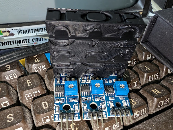
The idea of keeping this as something that anyone could build from easily available parts, they were looking at some cheap light sensor modules from Amazon.
These seem to be available in two types, one using a photo diode, and one a light dependent resistor.
I took some photos and reverse engineered the schematic.
One moment please.
This is the photodiode version, it uses half of an LM393 dual comparator. One input is a potential divider containing the photodiode, the other an adjustable threshold voltage. The output should be 0V or 5V, depending if photodiode input is higher or lower than the threshold.

The light dependent resistor version is very similar, but is missing the 4th pin to monitor the analogue voltage divider (which we don't need anyway).
Both versions have a capacitor across the light sensor element to smooth the response. That's not ideal in our application, and it might help to remove those.
I did some testing with both versions and found the photodiode one was no good, it could not detect the difference between a black and a white square on one of my monitors. I tried replacing it with a couple of different photodiodes and phototransistors I had, but none of them seemed any good for this application.
The LDR version performed a lot better, and seems to be the best option. TFW8b's came to the same conclusion, so LDRs it was.
TFW8b got to work building up a transmitter module using 9 LEDs in a 3D printed mount. (the 3D models for all of these are available on from TFW8b - https://www.tfw8b.com/introducing-jelly-load)

A similar mount was then made to take 9 of those light sensor modules.
I said 9.

Thank you.
During testing, it became apparent that the response time was slightly different for each of the sensors.

You can see the ends aren't all level, so a slightly different incident angle gives a faster or slower response. There are also the tolerances of the parts involved and the adjustments of the threshold level.
In order to get around that an extra delay was added before the clock was toggled to give the data lines time to settle. Good for stability and reliability, but unfortunately means a lower eventual data rate.
With the delay added, things started working well, so the next step was to add in the video element.

The receiver is currently quite bulky with those boards and wires, so the best result seemed to be standing it on a phone or tablet and playing the video on that (suitable zoomed in).
I wrote a bit of test software which just echoed what each sensor was currently reading, so they could be adjusted and aligned correctly.

TFW8b was able to keep knocking down the delay times to see how fast things could be pushed.
Sending data via YouTube
With real YouTube videos, it is now looking like about 4 bytes per second is reliably working.
That means a 3.5K program takes about 15 minutes to load. Not too far from the target we were aiming for, and the full sequence of events.
PRG file 🡆 LEDs 🡆 Camera 🡆 YouTube 🡆 Sensors 🡆 Userport
Some sample videos have now been uploaded, with the Jelly Load square top left.

And one showing the receive program in action.

If anyone wants to try this for themselves, the 3D models and VIC20 programs are available form links at the bottom of this page from TFW8b:
https://www.tfw8b.com/introducing-jelly-load/
There is also a video quite to building a receiver for yourself, including an 8K expanded VIC20 game sent via Jelly Load to you to "download" and play.
We plan to make an all in one module at some point with 9 sensors and a single adjustment pot, as well as receive software for the PET and C64. I am also working on a direct VIC20-VIC20 version, a sort of "laplink cable" that can be used to transfer software between machines in a much slower and more inconvenient way that just putting it on an SD card.
Advertisements
To load these programs, you will probably need a Penultimate +2 Cartridge
There is also my store with the full range of Minstrel and Mini PET accessories. Mini PET kits are all sold out now, but I do still have some Minstrel 3 kits left, which will last until I run out of Z80s.
I can ship worldwide, use the link at the top of the page to contact me with your location and what you want. Sorry I have to keep saying that. I am working on an alternative.

All the links can be found here:
Patreon
You can support me via Patreon, and get access to advance previews of posts like this and behind the scenes updates. These are often in more detail than I can fit in here, and some of these posts contain bits from several Patreon posts. This also includes access to my Patreon only Discord server for even more regular updates.
