My 1581 clone is now complete and working well. It took quite a while to get there. There were three more Patreon posts covering the progress, but rather than post those individually and have people suggest things that I have already tried, I thought it would be best to roll them all up into one post.
I am sure this will be long enough, but if you want even more detail, check out the original Patreon versions of parts 2, 3 and 4. Please consider supporting me there if you think four of these posts a month is worth a pound, thats 25p a post.
The story so far.....
Are you sitting comfortably? cup of tea? some of the posh biscuits? OK, let me begin.
I have built a 1581 clone, put it together with a working Amiga floppy drive and it didn't work.
I know now some of the problems at this point were because I didn't have any properly formatted disks, but even going back I was still getting "74 Drive Not Ready" errors most of the time.
At this point I will skip over lots of things I have tried to get reliable operation.
- Two different C64s
- A VIC20
- A different drive cable
- Other disk drives
- Other drive cables
- Other Rockwell R6502 chips
- Some MOS 6502 chips
- Making W65C02S chips work (long story, didn't work)
- Other 8520s
- A 6526 (with the jumper removed)
- Other WD1770 chips
- A VL1772 (with the jumper removed)
- Other ROM chips
- ROM with Jiffy DOS
- Other 65526 RAM chips
- 6564 RAM chip
- Different power supplies
- Standing on one leg
- Several different T shirts and one red sweater
I also tried dozens of different floppy disks, all of which had been tested in a PC and/or Amiga
None of the combinations were reliable.
Amiga Drives
This was frustrating because the drives and disks appeared to work fine in Amigas or elsewhere.
When looking through the 1581 service manual, I found a reference to the part number of the drive actually fitted to real 1581s.
This shows 312550-01.
I have seen references that say that is for the A500 and the 1581, but checking the Amiga 500 manual, that shows a different part number, 312554-01.
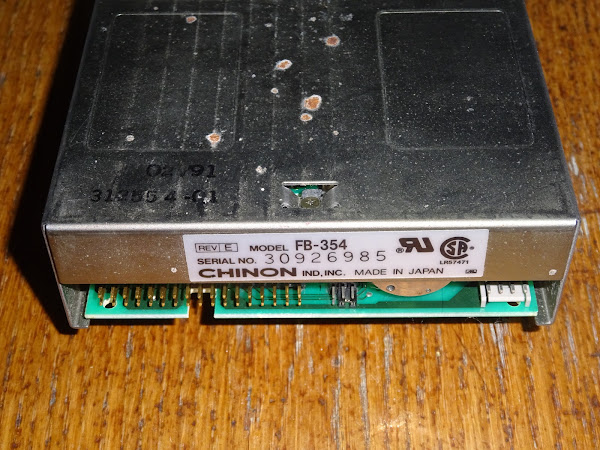
Both seem to be Chinon FB-354.
So, I found a Chinon FB-354.
This one is working, and is direct from an A500 I have just opened up.
You can see it is actually stamped with the Commodore part number, 312554-01.
So, does it work?
No.
Well, sort of. Like a couple of the other drives, it works sometimes, but the disk change is not recognised properly. It successfully listed the directory, but when I changed disk, it went back to drive not ready.
There are various jumpers on the Chinon drive. Maybe 312550-01 and 312554-01 are the same drive but the 312550-01 version for the 1581 had different jumpers set?
The only picture I have seen online of a real 1581 seems to have a Chinon F-354E. Maybe that is different again?
I had been waiting for one of those to come up on ebay, but the ones on there are a bit too pricey and I am fairly sure it would not be any better.
I think it is down to at least one of the following:
- The original drives were jumpered differently for the 1581 vs the A500 and we don't know how
- There is an error in the schematics the clone PCBs are based on
- There is an error in the clone PCBs
- There was a mod to the production units not included in the schematics
- The 1581 never worked properly in the first place, maybe it was not around long enough to fix?
- Maybe this is why people bodged drive reset buttons onto them?
Time to look online and see if there are any answers.
Samsung SFD-321B
It seemed people had been having success with a PC drive adapter board and a Samsung SFD-321B jumpered for PC.
I had a look and the only drives I could fine quickly and cheaply were ones that had been converted for use with Amiga. That seemed a good bet as I could try that and if it didn't work, I could convert it back to PC.
I tried it.
It didn't work.
Well, as before, it worked some of the time, other times would just get stuck with drive not ready etc.
This is the drive as supplied, with the mods to work on an Amiga highlighted.
I found a few "how to convert an SFD-321B to Amiga" guides, and followed them in reverse to get back to the standard PC configuration.
I went into more detail in the original Patreon post, but I will skip over it now, for reasons that will be clearer further down the page.
Tim and other 1581 replica builders all seem to be using an adapter board, and Tim included the PCB of the one he used, so I build that up. (Thanks again Tim, Thagim)
This adapts a "PC style" drive to work with the 1581.
There is apparently a known issue with using this with a Samsung SFD-321, it needs an additional pullup to one of this pins that are no longer driven by the 1581 board, so I fitted that before I started.
Time to test it out.
Finally a successful format and directory.
I had a few disks that would not format, but cleaning the head and adding some lithium grease to the worm gear seemed to improve that.
I tested that quite a lot, and it seemed to be working well, detecting disk changes etc.
I used CBM Commander to create a real floppy disk from the .D81 image of the 1581 demo disk.
It took over an hour, but at the end, all was good.
The images have to be D81 files, don't try a D64 as it won't work.
Note that Epyx fastload does not support the 1581 drive, so I had to remove that in order to load files. It is understandable, the code it sends to the drive is designed to run on a 1MHz 6502 with a 6522 wired in a particular way, and here it is trying to run on a 2MHz 6502 with a 8520 wired differently. (this was before I added the Jiffy DOS ROM to the test C64)
Not quite plain sailing, but I got there in the end.
That seemed to be working OK, so I started looking to make some sort of case for it, I thought a nice option would be mounting it on a sheet of perspex. All I needed to do was order that, drill it, mount it, make it look nice, take some photos and redo some of the screenshots with the patched ROM clearer display on the C64.
Easy. What would possibly go wrong.....
I ordered the perspex, but it was taking a while to arrive, and so I started working on different things, and no longer had the C64 or 1581 on the bench when the perspex arrived.
I put it to one side to pick up when I had some time and some space.
Building a sort of case
Roll on a month or two and it was now time.
I started by marking out the holes on some tape in not quite the right places.
I then drilled the holes not quite where the marks were, so they will end up exactly where they should be.
Actually, 7 out of 8 did. I call that a result.
(the wire mods on the back of the PCB are from some of the testing I was doing to try to get W65C02S chips to work before I got the Samsung drive, I couldn't, so I have skipped over those and everything is back as it was)
I missed one of the floppy holes by quite a margin, so I stuck one of the feet over it.
That seems fine mounted on some pillars.
OK, that looks good, now I just need to sort out the cabling. I need to run a 34 way ribbon from left to right, and make it look better than this.
I had tried various arrangements, with the drive on either side but it still required a number of folds and did not look great.
I had an idea, but before I started to make any changes, I thought I would check everything was still working.
Oh dear. I was back to getting "74 Drive Not Ready" and various empty responses.
Here we go again, back to the same problems.
I went through the same tests again, and still problems (yes, I tried going back to the standard ROM without Jiffy DOS, and with and without the fastload cartridge, in case that made a difference - it didn't).
OK, let's do this properly
This is getting silly. I decided to have a proper look at what was actually going on with the adapter and the various modifications it makes.
"Drive not ready", that basically means the ready signal is not being set or not being read correctly.
According to the manual for the Samsung SFD-321, this signal will be active (low) when the drive has spun up the disk and it has spun around at least twice.
The problem is, the 1581 doesn't turn on the motor, so it doesn't spin the disk, so it doesn't activate the ready signal, so the drive is 74 Drive Not Ready.
It gets a bit messy because the drive can generate either disk change or ready, and send that to pin 34. The 1581 however requires disk change and ready, so that is what the adapter board must be doing.
It has a 74HCT02 quad OR gate chip on there.
This is arranged as a flip flop to generate the ready signal based on the motor control line and the index hole detection sensor (which pulses once per revolution as an optical sensor picks up a hole in the spinning disk)
It generates a ready signal when the disk is spinning and an index pulse has been detected, and clears when the motor is turned off. Similar to the way described in the drive manual above.
Floppy drive connections
This shows the connections to the floppy drive. I am specifically looking at the Samsung SFD-321B, although most are similar.
First, all of the odd numbered pins on all of these interfaces are ground, so those are not shown on any of these diagrams.
Secondly, the In use, and Drive select 2 and 3 pins are not connected to anything, at either end, so they can be ignored.
There are three sets of jumpers, as explained in the drive manual.
Drive select has two jumpers DS0 and DS1. If you want the drive to be active when the Drive Select 0 signal is active, solder blob jumper DS0, Alternatively if you want to use Drive Select 1, blob jumper DS1. For reasons I will not go into here, the PC and its infamously twisted floppy cables use DS1.
Next is a choice of which signal to feed to pin 34, Disk change or Ready. The PC uses Disk change.
Finally the slightly misunderstood pin 2. This is used as part of the density select for the drive. There are various options for 1MB (double density, 720K in PC terms) and 2MB (high density, 1.44MB in PC terms) and also 1.6MB (?)
The option we need here is OPA and OPB open, 2MB HD if the disk has a second hole in it, 1MB DD if it doesn't. (interesting...... see the next post)
This shows the drive in default PC state.
I had previously concluded that the way to get this to work was to have the drive in PC mode like this, and use the adapter board.
I think it is time to re-investigate that, as some of it doesn't quite line up now.
The general advice online was that a 1K pullup is required to be added to pin 2. Now, this is the pin which is part of the density select option. Fair enough, but hang on, that connects to jumper OPA, which is not fitted, so it is going nowhere. So in this application it appears to be pointless?
It may be required on other drives, or other revisions of the drive, but in this case it is doing nothing. And no, I didn't get it wrong and it should have been pin 2 on the 1581 side, as that is the output of the 74HCT02, which is a strong CMOS drive and definitely does not require a pull up either.
I checked all the other signals, and all the ones that are inputs to the 1581 already had pullups on.
Given that, I decided to investigate further into this and it seemed like I could remove that board from the equation, and try to get the drive working as is.
Looking through schematics of what the 1581 generates and what the drive expects, this is what I have concluded I need to do.
Drive select is easy, DS1 is not connected on the 1581 side, and DS0 is wired to ground, so I need to use the DS0 solder blob.
At this point, I had a wire soldered to the Motor On signal to drive the front panel LED. This is normally lit when the drive is selected, and since DS0 is wired to 0V, it is always selected, so it always on. That is not ideal.
I did look at various options for replacing the LED with a tri-colour one, but the orange was never very good when both were lit, so you can't really tell what it was meant to be showing, so I will stick with the two 3mm LEDs, that is working nicely.
I thought it would be useful to show when the motor was spinning, as it is not a good idea to remove the disk when it is. The Motor On line seemed ideal for that. It is driven low by a 74LS07, so that should be fine to drive an LED.
The anode of the LED is connected to 5V, and the cathode goes via R3 (160Ω) to the controller chip where it gets a presumably buffered version of drive select. I lifted one side and wired that to the Motor On pin.
Now to the issue of Disk Change and Ready. The controller generates both, and the 1581 needs both, so let's give it both.
Ready is selected for pin 34 by moving the 0Ω link to the RDY pads. Disk change is picked up from the pad above, and wired to pin 2, on the pad of OPA, which is not fitted (= automatic density selection).
So that is my completed re-wiring of the drive.
Hang on, that's now the same as the "SFD-321B in Amiga mode" I had before.
Oh well, at least I have worked that through and I am happy that it makes sense.
But does it work?
No.
I did try it without the LED mod, just in case. Didn't make a difference.
In all these cases, when I say it doesn't work, I mean it works sometimes, not other times, and rarely after a disk change.
More things to try
Checking online, several 1581 problems were put down to the power supply. I am using an external 5V supply, which I know is good, and the voltages are reading fine all over the board and the drive.
I do see two electrolytic caps, and I am sure someone is going to suggest changing them, so I did.
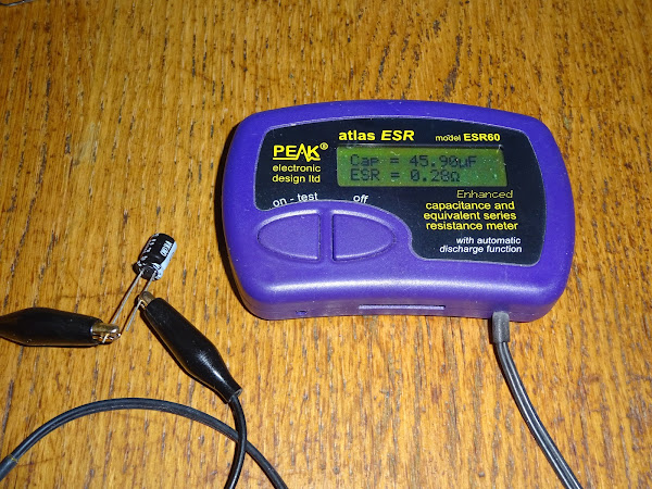
They were quite small caps, but there is nothing in the way, so I fitted physically larger ones which is generally a better option. They were 33µF 25V and just across the 5V rail, so the precise value is not important. (this is a 5V only drive)
I went for some nice Nichicon 47µF 100V caps I had to hand, overkill but should do no harm.
Were the originals bad?
No.
Where the new ones better?
Yes.
Did changing them help?
No.
I went back over things again, and reading back over the floppy drive datasheet, I noticed that lots of things were timed from the drive select line going low.
I wondered if it being permanently low might be affecting things?
Then I thought about the Motor On signal, that is low when the drive should be accessed, so could I maybe use that as a drive select?
That also meant I could reinstate the original drive LED, since it would now only light when drive select was low, which was now motor on.
Did....
Did that....
I'm scared to look.
Did that fix it?
Oh, yes, it did.
Great.
This is now the state of the modifications.
Disk change and ready are as before. The LED resistor is back how it originally was, no change there.
Both drive select jumpers are clear, and there is a link from Motor On to the common side of the two Drive Select jumpers.
Completing the case
There is no mod board in place now, the ribbon cable is connected directly to the 1581 board, but still doesn't sit right.
I decided to try a trick from my PC building days, you can reduce the bulk of the ribbon cable by separating it into a number of smaller cables. Using a screw driver to separate it into 4 wire sections (and two 5 way in the centre since 34 is not a multiple of 4), it can then be bundled together.
With a few cables ties in place that looks quite neat, certainly better than the flat cable.
It nicely obscures the alternative resistor placements.
One final touch is a second piece of perspex on the top, picking up on the four mounting points for the drive controller PCB.
That leaves space above the drive and the controller card for some airflow.
Looks rather splendid, doesn't it?
I have now tested this quite a lot again, and it seems to be working nicely.
For best results with an unformatted disk, turn the drive off, and back on, and then insert the disk and proceed to format. It seems to get confused when it does not read correct formatting, and this seems to work with most of the good disks.
I have been using the performance test from the 1541 diagnostic cartridge, that seems to be the fastest way to kick off a format. If it fails, say no to "continue" and then yes to "again" and it goes around again.
When it does succeed, you can let it run through the test. Not sure how useful the results are as the expected disk geometry is different, but it gives the disk and the drive a bit of an exercise and if it passes the disk it is ready to be reused.
I have been using CBM command to move things around between an SD2IEC and the 1581.
Here is an arty shot showing the screen reflected in the perspex on the top whilst copying.
CBM Command has the ability to copy D81 disk images direct to real disks. I was looking for some games that were originally on multiple 1541 disks and had been converted to single D81 images. Thanks to CommodoreBlog for suggesting some.
I had left the Jiffy DOS ROM in the 1581 and with the matching ROM in the C64 it was now running faster. It took about 20 minutes to create a disks, it was well over an hour when I first had this running on the standard ROMs.
That looks promising.
I am not very good at games, but they all seemed to load and play.
Another use for the larger capacity disk is you can put loads of PRG file games on one disk. I put FB64 on first, so you can load that with LOAD "*",8 (or Commodore + Run/Stop with Jiffy DOS).
I have just stared with I few I had on an SD card, including the freeware demo of PETSCII Robots which only has a few levels, so there are only a handful of files that can be extracted from the D64 to fill the disk.
I think the 1581 saga is now complete. It seems to be working nicely now.
Update
It is still working this morning, so hopefully that is resolved now*.
I am not convinced the disk change notification is right, since the motor will not be spinning, but it seems to be working in practice, and I can use the @I command to reinitialise the drive, is press the drive reset button if I decide to fit one.
* Your milage may vary. Things that fix my problem may not fix yours. No guarantee mine will be working tomorrow. Things may be screwed up as well as down.
Adverts
I understand now is not the best time to be selling on an American site, but I am from the UK. All products are designed, built and shipped by me, here in the UK.
My listings are on Tindie, but if you prefer, DM me or use the contact email on my site to order direct.
All international orders may be subject to local tariffs, taxes or duties, and handling fees etc. Please be aware of this before ordering.
There are a selection of other repair and upgrade parts for various machines, many of which can be seen on this PET 2001 board.
There are also Minstrel 2 and Minstrel 3 kits and accessories available.
You can now get a Minstrel 2 kit for $200. Same as the 1980 pricing for the ZX80 kit on which it is based.
Or if you want ZX81 compatibility, you can get a Minstrel 3 kit for $200
Patreon
You can support me via Patreon, and get access to advance previews of development logs on new projects and behind the scenes updates. These are often in more detail than I can fit in here. This was actually three Patreon posts rolled into one, so a lot got cut out. This also includes access to my Patreon only Discord server for even more regular updates.