I know I have several of these, but I couldn't find any when I was working on the previous post where I looked into Kempston compatible joystick interfaces - http://blog.tynemouthsoftware.co.uk/2024/05/minstrel-joystick.html
I have now found an actual Kempston joystick interface.

Turns out Kempston Micro Electronics were actually based in Kempston, Bedford, UK.
All the best hardware comes from companies named after their location.....

This is a two chip design. Both slightly unusual choices.

Problem 1
The one on the right is a 4071 CMOS quad OR gate, why not use a 74LS32? Maybe they were cheaper, or they liked the slightly different pinout? (the outputs are all on the middle pins 3,4,10 and 11).
CMOS and TTL do not usually mix, but you can generally drive TTL inputs from CMOS outputs, just not the other way around. The inputs are all direct from the NMOS / CMOS Z80, so it should be OK, but it does no seem ideal.
The chip on the left is a 74LS541, also unusual. Like many of the 500 series, this is a version of another chip with an alternate pinout, in this case a 74LS241. The 500 series often all the inputs on one side, all the outputs on the other, to make PCB layout neater, I like the 573 and 574 for that.
I will give them credit, the layout is indeed very neat. All single sided, with no jumper links.

Problem 2
The decoding is a little lacking. They have used A5, A6, A7 and /IORQ all low, which responds to an IO request over the address range of 00-1F (0-31). However as well as the read requests it needs to respond to, it will also respond to writes and interrupt acknowledge signals. This could cause a bus conflict as both the Z80 and the 541 buffer will be writing to the databus, so is not ideal. They had a spare OR gate, so they could have added /RD low as an extra condition to fix that.

Problem 3
Also unusual is the way the 9 way D joystick port is wired. The common on the joystick port, pin 8, is connected via a 4.7KΩ resistor to 5V, and the autofire power, pin 7 is not connected.
This interface is (by definition) Kempston compatible, so follows the standard protocol of a byte read from address $1F / 31, with the bits set as 0 normally and 1 when active.
To achieve that, with the non-inverting buffer chip they have selected, all the pins are pulled low with 10KΩ resistors, including the three unused bits. The switches in the joystick are used to switch to 5V (via the 4.7KΩ resistor). These signals are then passed though the non-inverting buffer when the port is read.
That arrangement isn't really Atari / Commodore compatible, because the common pin 8 is normally connected to 0V and pin 7 supplies 5V for autofire circuits etc.
Pin |
Kempston |
Atari / Commodore |
|---|---|---|
1 |
Up |
Up |
2 |
Down |
Down |
3 |
Left |
Left |
4 |
Right |
Right |
5 |
- |
- / Paddle / Fire 3 |
6 |
Fire |
Fire |
7 |
- |
5V |
8 |
5V |
0V |
9 |
- |
- / Paddle / Fire 2 |
That means most (if not all) autofire circuits will not work. Some will do nothing, others may do odd things like fire continuously, or fire when moved in any direction. Some may even be damaged by the reverse polarity.
What's that you say? you want a blog post with a deep dive into autofire circuits? One day maybe.
Problem 4
Having the common wired directly to 0V would mean you should get pretty much 0V at the input of the logic gates. Any resistance due to the switch contacts, cables and connectors should be insignificant in relation to the pullup resistors that are typically 10KΩ.

In a worst case, with a really poor cable and bad contacts you might get 100Ω combined resistance. With a 10KΩ pullup, that would still give an output of 0.05V, and in practice, it is likely to be only a few ohms, so only a few mV above 0V.
Kempston have fitted a 4.7KΩ current limiting resistor in the common line. The value of this is quite close to the 10KΩ pull downs resistors. This will form a potential divider and the voltage input to the buffer chip will not be 5V when you hit fire or move the joystick. Normally you would plan them to be orders of magnitude apart so the potential divider impact would be insignificant.
With just fire pressed or a movement in a single direction, the potential divider created by the 4.7KΩ resistor and a single 10KΩ pulldown will give about 3.4V. Not 5V as would be ideal, but well in the range of logic 1 for a TTL chip (which should be anything over 2.0V).

With fire pressed at the same time as moving in a direction, or a diagonal movement which will register as two directions at the same time, there will be two 10KΩ pull downs in parallel.
I have redrawn that with the switches removed and replaced by shorts or gaps, so you can see the resistors that are still in circuit and the the ones that are not.

This means the potential divider is now 4.7KΩ and 5K, so the output voltage would be about 2.6V. Again not ideal, but still just about within range.
In the (admitedly rare) case of fire and a diagonal at the same time, would be three 10KΩs in parallel. That would make their combined resistance 3.3KΩ, giving an output voltage or around 2.1V, very close to the 2.0V threshold. If the 5V line dropped only slightly to 4.8V, the input to the logic gate would drop below 2.0V and into the no mans land between logic 0 and logic 1, so it may not always read correctly if you press fire when moving diagonally.
Could they have done it differently?
I am not sure why they decided to deviate from the standard established by Atari in 1977. They could have used a 74LS540 instead of a 541. That is an inverting buffer, so they could have implemented a more standard interface with pin 8 as 0V and pin 7 as 5V, and pullups on the inputs up to 5V.
Something like this:

I have left it with a 4071, but ideally a 74LS32 would be more appropriate.
This version has no extra parts (in fact there is one fewer part as there is no need for the contentious 4.7KΩ resistor) and makes it more compatible with other 9 pin D joysticks. I guess they must have had their reasons.
I also used the spare gate to add /RD to the decoding to stop it responding to writes and interrupt acknowledges. Again, that's for free if they had chosen to, it would not add any additional propagation delay, and I think would have routed neatly without a need for a jumper link.
Actually, I've just checked and the 541 has two enable inputs which are ORed together, so both have to be low to enable the buffer. They have them both wired to the output of the OR gate address decoder, so they could have just wired one of them directly to /RD and not even needed the spare gate.

So in several ways, the Kempston joystick interface is not the best Kempston compatible joystick interface.
Problem 5
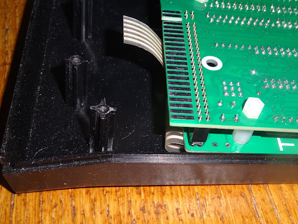
This particular example also has one more thing against it, a damaged edge connector.

I have picked up a few interfaces of various type with edge connectors that are broken like this one. The material seems to be quite brittle and the connector cracks all the way along one side. I guess someone left this connected to their Spectrum and then it got knocked.
Advertisements
My own take on a Kempston compatible joystick interface is the Minstrel Joystick.

This is available from my SellMyRetro store
- Assembled - https://www.sellmyretro.com/offer/details/64329
- Full kit - https://www.sellmyretro.com/offer/details/64328
- PCB only - https://www.sellmyretro.com/offer/details/64330

Those and the full range of Minstrel and Mini PET kits and accessories are available form my SellMyRetro store.

All the links can be found here:
Patreon
You can support me via Patreon, and get access to advance previews of posts like this and behind the scenes updates. These are often in more detail than I can fit in here, and some of these posts contain bits from several Patreon posts. This also includes access to my Patreon only Discord server for even more regular updates.