Sunday 25 June 2023

Converting a multipart game for the VIC20 - Galaxia

During the process of selecting games to add to the new Penultimate +2 cartridge, we have come across a lot of games that load in multiple parts.

These are games where a program loads from tape (or disk), and then goes on to load one or more additional parts. This was quite common in the day due to the memory limitations of the VIC20.

The first part would display a title screen or some instructions or define some graphics characters (or various combinations of the above). Once those have been displayed, the game itself could then be loaded, overwriting all of the previous data and leaving as much room as possible for the game.

Multipart games need to be converted to cartridge images, and that often needs a custom approach for each one due to the ingenuity (or craftiness) of the original designers.

Over on my Patreon, I have written quite a few posts about some of the different techniques found during converting mulitpart tape games for the VIC20. This is one of the later posts, but seems a good place to start as it covers one of the easier conversions in more detail.

Today's game conversion is Galaxia, I wonder if you can work out what sort of game it is based on the cunningly disguised name?

Step one is to check out the source, here a D64 disk image. I load it on Vice, in this case with the following command line

xvic -memory none "Galaxia (1983)(Romik).d64" 

This means start the VIC20 emulator, set the memory to unexpanded and auto-load the Galaxia disk image. Note this is "none" and not 0. xvic -memory 0 sets the VIC20 to have RAM in block 0, the 3K expansion. The number of times I have typed memory 0 by mistake these last few months......

This is to check the source file works. To check if the game is any good, and to check it isn't just the same game with a different name (looking at you, Jeff Minter).

In some cases, the tap or d64 files will contain only a single PRG file, this is not going to be one of those, but that's fine. If it was a single PRG, that would probably be the version that had been archived.

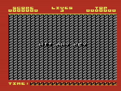
The title screen loads up, press fire and you are into the game, a sort of pillar-boxed version of Galaxians. (did you guess right?)

No time for playing games now, but nice that it is wishing me luck with the conversion.

This all seemed to happen in one go, so is it just a single file then?

There is a common trick of using one program to display a title, maybe some instructions, and sometimes pre-load graphics, and then to load a second part which will overwrite the first, it's job now having been done. This is to cope with the lack of memory in the unexpanded VIC20.

The first of these is very small, so presumably a loader, and the second would be the game itself.

It is always worth loading these individually to see what they are.

In the simplest case, the first will be a title screen and maybe instructions, and the second will the just the game itself, and often if the gameplay is obvious enough, you can ignore the loader and just use the second part, the game itself.

Here, loading the first part, it shows just a SYS command, so it is assembly language program.

Incidentally, in case anyone isn't familiar with it, I used a trick to load the file. The spacing of the directory listing is such that you can cursor up and overwrite the start with the line with LOAD, and add ,8,1 after then name and overwrite the PRG with spaces, then press enter to load the file.

That is sometimes useful if the name is long or difficult to retype due to unusual characters.

Loading the program is fast as there is not much too it. Listing it shows a single line

10 SYS 4112

Normally what happens here is there is a large machine code program directly following the one line BASIC program in memory, all loaded in a single go.

To view what is loaded, I use the monitor in the Vice emulator, and the command

m 1000

To display the memory from 1000 (4096 in decimal) onwards.

There is something that looks like code there, so I use the command

d 1010

To disassemble the code from address 1010 (4112 in decimal) onwards. This is the last one I will mention in decimal, just because it comes from the SYS(4112) command, which is in decimal and stored as the characters '4', '1', '1' and '2' in the file. The rest of the time, assume everything is in hexadecimal.

That is all the code that runs from there. Interrupts are disabled, then 20 bytes are copies from 1020 to 0140. 1020 is immediately after this code, and 0140 is in the processor stack, but in an area not required for the moment.

The tape buffer from 033C-03FB is also a common place to hide code so that it won't get overwritten by the second part loading (unless you are loading from tape, obviously....).

Once the code is copied, the last line jumps to 0140 and runs the code from there.

In vice, I set a breakpoint on address 0140 with the break command.

break 0140

Once that was set, x was used to exit back to BASIC and RUN the program.

Once it had copied the code to 0140, it did the jump and them the monitor kicked in and I was able to disassemble the code at 0140 with the command 

d 0140

This code uses three kernal ROM calls to load a file. The first is to FFBA, SETLFS. This sets the three zero page parameters based on the values in registers A, X and Y, which are loaded before the call.

  • A, LA = 8, logical device (i.e. the channel in the open command)
  • X, FA = 8, device ID = 8, hard coded to the usual default drive, but not always. (trap for young players, this won't work from drive 9)
  • Y, SA = FF, secondary address = FF (tested for 0 or not 0, but normally it is set to 1 rather than FF, but it doesn't really matter)

The second call is to FFBD, setnam. This sets the namename for the load command based on registers A, X and Y. A contains the length of the filename, and X and Y are pointers to the filename

  • A, FNLEN = 8, 8 character filename
  • X, FNADDR (LSB) = 3A
  • Y, FNADDR (MSB) = 10

Together this sets the filename to be 8 characters from address 103A, which is at the end of the area of program memory.

That can be checked with another M command in Vice M 103A

m 103A

The 8 characters are ZZGALAXI, the name of the second file

The final command is FFD5, LOADSP. This loads RAM using the parameters previously set, from device ID 8, with filename ZZGALAXI. Here only register A is used. X and Y hold the load address, which is ignored when SA above is not 0, and the load address from the file is used instead.

  • A, VERCK = 0, 0 means load, anything else means verify.
  • X, MEMUSS (LSB)
  • Y, MEMUSS (MSB)

The final line of code is a jump to 1A26, presumably the initialisation function somewhere in the code.

So, all in all, that does the equivalent of LOAD "ZZGALAXI",8,1 then jumps into the code to launch the game.

The file is 0E00 bytes long, so exactly fills the available space between 1000 and 1E00 where the screen starts. Things must have been so tight that there was not enough space for the usual 10 SYS xyz command at the start.

Normally with these conversions there is a bit more to do in replicating what the first parts of the loaders do. In this case it is just copying a block of code into RAM and running it.

I have created various loader cartridges over the years, and I just pick something similar and adapt it. The cartridge code need to call various initialisation functions from the kernal to setup the VIC and IO chips and initialise the memory etc. 

Looking at the VIC20 KERNAL, pretty much the first thing it does is check for a cartridge.

Unfortunately, for some reason it does this with JSR, rather than just having those few lines of code directly in place.

This wastes a few cycles and a few bytes unnecessarily, but more importantly, it means you need working RAM in the first 1K in order to boot a cartridge, which is a shame for things like Dead Test as nothing can run on a system with bad RAM in the first 1K. (JSR pushes a return address onto the stack at 01FF, and RTS pops that back off to go back there. If the RAM is faulty, the address popped off could be anything).

The cartridge borrows the initialisation code that runs when a cartridge is not present.

Next is a simple block copy routine to copy the code into the appropriate location in RAM.

Normally BASIC is also setup and the newly loaded code relinked and then run as if the user had typed run. However, here, that is not necessary as it just need a jump into the copied code as the original loader did.

I will cover that in more detail in a future post on a game that needs it.

The loader and the block of code together are less than 4K, which is ideal as this now fits into a 4K slot in the Penultimate+2 ROM.

That loads and plays nicely. Although, sadly only in PAL. On an NTSC VIC, the screen is positioned off to the side with no adjustment as far as I can see (some games use arrow keys or joystick to reposition the screen).

I will look at a possible NTSC conversion in future.


Advertisements

Penultimate +2 Cartridge

The Penultimate +2 Cartridge with the Galaxia and a host of other games is available to pre-order from The Future Was 8 bit:

More info in a previous post:

http://blog.tynemouthsoftware.co.uk/2023/06/penultimate-plus-2-cartridge.html


Patreon

You can support me via Patreon, and get access to advance previews of posts like this and behind the scenes updates. These are often in more detail than I can fit in here. This also includes access to my Patreon only Discord server for even more regular updates.

https://www.patreon.com/tynemouthsoftware

Sunday 18 June 2023

Diagnosing IEC serial bus faults on the VIC20 and C64

One of the problems you get on Commodore machines is the dreaded "DEVICE NOT PRESENT" error, or just hanging up when trying to load.

That usually means either there is a problem with the C64/VIC20 or with the disk drive (or rarely the cable between). But it is difficult to know which.

Ideally, you have access to another drive or another Commodore machine to test with to narrow it down and identify the problem.

Because of the way the IEC serial bus is wired up, it is actually possible to get it to test itself, or at least some of it.

There are six signals on the IEC bus. One is ground, another is reset, so that leaves four we are interested in. One, ATN, is output only (ignore what it say above about in/out, that just means it is wired to a pin on the userport), another SRQ is input only (and only used on the C128/157x), and finally the two main signals, CLK and DAT, which are both inputs and outputs.

This post is written with the VIC20 in mind. Like any good Usborne programming book from the 1980s, there are notes at the end to convert it for the Commodore 64. 

The VIC20 schematic is a little difficult to follow. 

I have tried to tidy up the schematic by removing all but the relevant bits, and adding missing labels.

It's probably easier if I redraw it.

This shows the outputs go through a 7406 inverter gate, and then connect to the bus pin. The inputs are also connected to those bus pins, so you can effectively read back what is being written to the outputs (but note these is a stage of inversion, so write a 1, read a 0 and vice versa). This is a sort of a built in loop back. 

The 7406 is open collector, so it can only drive the bus low. There are pull up resistors for to pull the bus high when no devices are driving the bus low. All devices on the bus should be the same, so there can never be a bus conflict (at least electrically - there can still be logical conflicts, but that's for the protocol to deal with).

First, unplug any other devices, first, then write to the output and read back the input, and make sure it is correct.

You can do this with a series of POKE and PEEK commands. Whilst doing those, you can also monitor the signals on the port itself to check it is following along.

If all the values are correct, then it is unlikely to be any of the chips inside the machine at fault, and more likely the drive or the cabling / connectors in between.

You get dry joints on connector pins on joystick ports a lot, but I don't think I have seen that many on the IEC connectors.

If those values do not agree, it is either going to be one of the two VIA / CIA chips, or more often the 7406 driver chip (particularly when it is the MOS 7707 version).

You can trace through the schematic and see where the signal becomes stuck high or low.

All signals are active low, so that means the output of the IO chip is high, and the output of the 7406 inverter is low, and vice versa.

On the VIC20, type the following to activate ATN (remember these are active low)

POKE 37137, 128

And to turn it off use

POKE 37137, 0

It is a bit more complicated for CLK and DAT as they use handshaking pins which are multifunction.

The VIA PCR uses bits 1-3 for clock out, and 5-7 for data out. To control them manually, bits 2,3,6 and 7 are all high, so bits 1 and 5 control the values.

POKE 37164, 220     - both off

POKE 37164, 222     - clock on

POKE 37164, 252  - data on

POKE 37164, 254     - both on

Reading the values is a little easier, just use 

PEEK(37137)

If bit 0 is clear, then the CLK pin on the bus is active (low). If bit 1 is clear then the DAT pin on the bus is active (low).

I have been through this process in various forms, trying to talk people through diagnosing faults.

I looked at trying to automate this, and put together a BASIC program.

The idea was it would cycle through all combinations of outputs, and show the inputs. If all was working, the inputs would follow the outputs.

ATN is only an output, so the input side does nothing. I did want to get it to display SRQ as an input, but on the VIC20 it can only trigger an interrupt, and you have to tell it to look for a positive or a negative edge. In practice, it only needs to trigger on a falling edge, but for the purpose of displaying that value, it's not easy to read the actual state.

The BASIC version was very simple, and it worked, but was a bit slow to update, so it didn't always look to be in phase.

I decided to rewrite it in assembler, and also add a bit more information to the screen.

My plan was the cycling through combinations would pulse the outputs at a set frequency, so you could monitor them on a scope.

I had tried using a FOR NEXT loop to delay the BASIC program, but that was no where near accurate enough. When I rewrote it in assembler, I added an IRQ handler routine to count the jiffy pulses.

I went for 1Hz for CLK, with half of that for data and half again for ATN

I picked those up on the ferrite beads, but you can use any of the IC pins of the socket itself.

I was very pleased with how accurate the timing worked out.

If one of them is stuck, you will see it not toggling.

You can also see the output on the screen, with a much faster update thanks to being written in assembler.

When the output is red, the matching input should be red,, and likewise with green. If there is a problem, the colour will not change when it should.


Where can I find the IEC port tester?

One problem with something like this is you need the IEC port to be working to load the test program to see if the IEC port is working.....

But fear not, the IEC port tester is built into the Penultimate +2 cartridge, so you can run it directly from there.

See http://blog.tynemouthsoftware.co.uk/2023/06/penultimate-plus-2-cartridge.html for more information.

So, what causes these problems?

In that case, it was a bad 7406. I knew that already as it was a chip I had removed from a C64 board because it had failed.

This is the MOS 7707, which is a MOS produced 7406 replacement, and for some reason, they seem to fail more than the standard 7406's.

A new 7406 was fitted to that board and the IEC bus started working again.

So why do they fail?

Well, both the 7406 and 6522/6526 chips have pins connected to the outside world on the rear connectors, and you can get static via those pins, or voltage differentials when things are plugged in when live.

Later in the life of the C64, Commodore started retro-fitting clamping diodes across those pins, to add protection. Presumably they had seen enough failures in the field to justify it.

They were later added properly to the C64C. One diode to ground, one to 5V, on each pin. These should stop any voltages outside of that range from reaching the pins of the chips.

Which was much neater when they were part of the design.

They also make a handy point to pick up the connections if you are fitting an internal SD2IEC.

See an old blog post for more info on that: http://blog.tynemouthsoftware.co.uk/2017/10/commodore-64-c-internal-sd2iec.html

C64 Pokes 

The same can be done on the Commodore 64, these are the PEEKs and POKEs you need:

You can do some simple tests by poking the 6526 from BASIC.

The port used by IEC is at 0xDD00, or 56576 in decimal.

The outputs go via a 7406 inverter (which often fails, especially if it is MOS part 7707 rather than an actual 7406.

You can test some of the pins by writing to the 6526 register and measuring the output voltages on the IEC port, and also on the 7406.

The outputs are read back from the IEC socket, so you can write to clock and data and read back to see if the values are being read back correctly.

Do all of these tests with nothing connected to the IEC port.

Google your mainboard part number to get a schematic to check the appropriate places to measure these values.

Bits #0-#1: VIC bank.

Bit #2: RS232 TXD line, output bit.

Bit #3: Serial bus ATN OUT; 0 = High; 1 = Low.

Bit #4: Serial bus CLOCK OUT; 0 = High; 1 = Low.

Bit #5: Serial bus DATA OUT; 0 = High; 1 = Low.

Bit #6: Serial bus CLOCK IN; 0 = Low; 1 = High.

Bit #7: Serial bus DATA IN; 0 = Low; 1 = High.

Bits 0-3 are used by the VIC and serial TX, so just leave those set to 1.

Bit 4 is the output for the ATN line. If you poke a number where bit 4 is high, the ATN pin should go low.

POKE 56576,7+8    (0000 1111)

then poke a number with but 4 low and the output pin should go high again.

POKE 56576,7                (0000 0111)

bits 4 and 5 are output for clock and data, bits 6 and 7 are the inputs.

If you poke the various combinations of outputs, you should see the inverse read on the pins and on the inputs.

POKE 56576,7+7         (0000 0111)
PRINT PEEK(56576)
199                                     (1100 0111)

POKE 56576,7+16      (0001 0111)
PRINT PEEK(56576)
151                                     (1001 0111)

POKE 56576,7+32      (0010 0111)
PRINT PEEK(56576)
103                                     (0110 0111)

POKE 56576,7+48      (0011 0111)
PRINT PEEK(56576)
55                                        (0011 0111)

If any of those read wrong, you should be able to tell if it is the 6526 or 7406 at fault, and replace the appropriate part.


Advertisements

Penultimate +2 Cartridge

The Penultimate +2 Cartridge with the built in IEC port tester is available to pre-order from The Future Was 8 bit:

More info in a previous post:

http://blog.tynemouthsoftware.co.uk/2023/06/penultimate-plus-2-cartridge.html


Patreon

You can support me via Patreon, and get access to advance previews of posts like this and behind the scenes updates. These are often in more detail than I can fit in here. This also includes access to my Patreon only Discord server for even more regular updates.

https://www.patreon.com/tynemouthsoftware

Sunday 11 June 2023

Fun with Crazy Cavey

Last week was the unveiling of the new VIC20 Penultimate+2 Cartridge, and for the next few weeks, I am going to look at some of the behind the scenes developments on the PU+2 from my Patreon.

As part of that, we have been collating lots of new games to add to it. Not just the usual classic cartridge games we have all seen, there is the complete Future Was 8 bit VIC20 release, including serveral new and exclusive titles - more on those in a future post.

We have also been looking for forgotten or overlooked titles. Ones you only had on cassette, ones you can't normally easily play on a VIC20. Hence the reason for all the "rummaging through VIC20 tapes" videos from TFW8b.

One game that was suggested was "Crazy Cavey". This is a quite a nice little platform game for the expanded VIC20.

The problem is, it can be tricky to load. I was told if you did a directory or anything before, it would fail to load. You had to load it first thing, otherwise it wouldn't work.

I wasn't sure what that was about, but I added it to the cartridge in the same way as all the other games and tried it out.

It started, but the background was wrong, and it immediately locked up.

I tried loading it from the file browser and it also failed in the same way.

Confused, I went back to basics (or rather back to BASIC) and tried loading it from there.

It loaded and worked.

I then did as I had been warned not to do and did a directory first, and then tried to load it, and it failed.

What? How? Why?

It seems the telltale of impending failure is when the start screen has characters in the background, rather than all black. But what is going on?

I thought it might have something to do with memory being uninitialised, and having the previous directory listing in memory might have caused a problem?

I added routines to clear the RAM before, I tried 00 and FF, but it didn't make any difference.

I managed to get it to fail in the Vice emulator (where these screenshots are from), by doing the directory before hand.

I also tried typing in a short program instead.

That also broke it.

I took complete memory dumps of the 64K RAM space before load, after loading and at the "HIT ANY KEY" page, both for a successful run and one that failed and tried to work out the differences.

I'll spare you the pain of those. Basically there were runs of bytes in zero page that were 00 in the working version, and different runs in the faulty one that were 20 (space). There were a few bytes different on the stack, and some of the code at the end was different, including the bit that had the JAM instruction that was locking things up.

I had noticed that during a normal load there was some corruption to the top of the screen. I had assumed that was redefined graphics or something, so hadn't thought about that, But what if what was on the screen might have made a difference.

I tried clearing the screen, and then loading, and ooh, it failed in a different way. (N.B. LOAD "CC",8 and LOAD "CC",8,1 make no difference here as the load address in the file is 1001, which is the same as the default)

It is always a good sign when you get something to fail in a different way. It means you must be messing about with the right thing.

Then it hit me, that wasn't graphics on the screen, it was code.

When the LOAD command was lower down the screen, the SEARCHING, LOADING and READY lines eventually caused it to scroll up. And when it scrolled the screen, it was wiping out 22 bytes of code for every line it scrolled up, and moving the rest to the wrong place.

Checking the file, it was indeed too long to fit into the RAM without overwriting the screen. It loaded at 1001 (the normal load address for an unexpanded VIC 20), and ended at 1EA8. The screen was 1E00-1FFF, so the end of the code was corrupting the screen.

(is it confusing that the 1001 here is in hex, but I used 22 in the previous line that was in decimal?)

That was not a problem immediately after a reset, as there would be no scrolling, and the READY prompt appeared just below the end of the code.

Doing a clear screen was also bad because the LOAD command would be too high, and the READY prompt would also overwrite some code.

So it seems if you want to load Crazy Cavey, you need to type the LOAD command after line 6, but not after line 14.

But why was it failing on the cartridge? That didn't type LOAD. That didn't scroll. Why did that fail?

Ah, well, that turned out to be a bit of code I had in place just before it ran the game. It calls a KERNAL routine to setup the VIC chip and other hardware, just like a clean power on. This of course includes clearing the screen. So that was wiping out all the code from 1E00 to the end.

I made Crazy Cavey a special case, any bypassed the screen clearing routine, and it now works every time.

Quite a nice game, I even made it past the first screen and onto the second level. I will enjoy playing that more later......er......I mean, I will have to do some further thorough testing.

It is now also working from the cartridge on real hardware (this time it is an actual photo of the TV)

Well, that was an interesting investigation. I had already started writing a post about how some VIC 20 games get around the memory limitations, but I thought this one deserved a post of it's own since it didn't actually get around them, it spilled over the edge and hoped you wouldn't notice.

If you want to see more of Crazy Cavey, you can watch Rod's play though here:

https://www.youtube.com/watch?v=HpvCFv8wEwU 


Advertisements

Penultimate +2 Cartridge

The Penultimate +2 Cartridge is available to pre-order from The Future Was 8 bit:

More info in a previous post:

http://blog.tynemouthsoftware.co.uk/2023/06/penultimate-plus-2-cartridge.html


Patreon

You can support me via Patreon, and get access to advance previews of posts like this and behind the scenes updates. These are often in more detail than I can fit in here. This also includes access to my Patreon only Discord server for even more regular updates.

https://www.patreon.com/tynemouthsoftware