The Minstrel 3 will run pretty much any ZX81 software. It will also work with most ZX81 add ons. The exception seems to be external keyboards that plug into the edge connector. There are only a few external keyboards like that for the ZX81, and for some reason, these do not work on the Minstrel 3.

I had a theory as to why this was, but up until now, I had not been able to test this because 1) I didn't have any ZX81 external keyboards, and 2) I didn't have suitable test gear to be able to test my theory. However, I was intrigued to find out what was going on, so I didn't let that stop me.
Step one was an external keyboard.
ZX-Key
The issue had been brought to my attention by David Stephenson of ZX81 Keyboard Adventures (and also author of Tut-Tut).
They had produced a ZX81 external keyboard called "ZX-Key"
https://www.zx81keyboardadventure.com/search/label/ZX-Key

This was based on an earlier design by Wilf Rigter (archived link)
The ZX-Key worked fine on a ZX81, but when they built a Minstrel 3, the ZX-Key didn't work with it.
https://www.zx81keyboardadventure.com/2019/12/all-new-zx81-minstrel-issue-3-kit.html
My assumption at the time was that this was due to the Minstrel 3 using 74HC logic, and the ZX-Key also using 74HC (or later 74HCT) logic, rather than both using 74LS logic as in the originals.
In order to test that theory, I thought I would go back to one of the 74LS based originals.
Memotech MT10
There were several keyboard options for the ZX81 in the 1980s, but most were replacement cases. The original mainboard would be installed in the new case, and the new keyboard was wired into the keyboard connectors of the original (such as the LMT 68FX2 I reverse engineered last week - that had a Spectrum board inside a new case, but you get the idea.)
http://blog.tynemouthsoftware.co.uk/2022/05/reverse-engineering-a-zx-spectrum-keyboard.html

The only (or at least the most popular) actual external keyboard released in the 1980s was the Memotech MT10. This was in the same style as their lovely 16K RAM packs and other add ons. It plugged into the back of the ZX81 and there was a separate keyboard, in a similarly styled extruded metal case with a full mechanical keyboard.

Sadly there is a Memotch MT10 shaped hole in my collection, and they rarely appear an ebay, and when they do, they are silly expensive.

Inside didn't look too complicated, four ICs and some diodes. So I thought I would make my own.
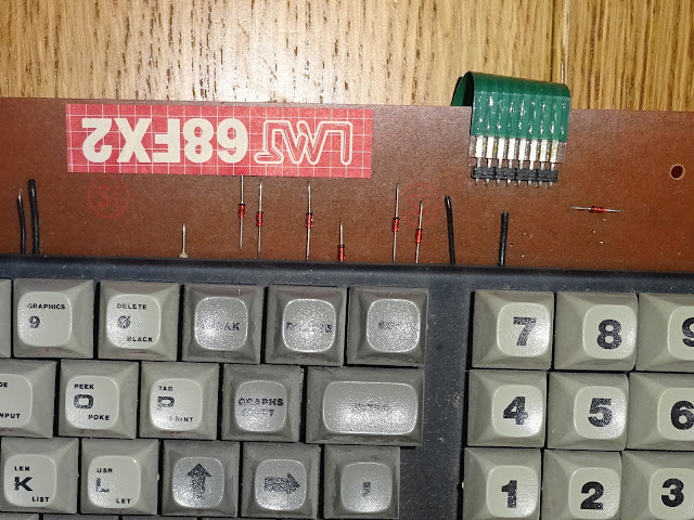
I couldn't find a schematic online, so I reverse engineered the design for various photos of the board. It was fairly straightforward.

First off, the "rows". These are buffered versions of the upper address lines. The diodes protect the IC in cases when multiple keys were pressed on the same row, which would short out the outputs of the 244 buffer. The original board has positions for through resistors and capacitors to ground. Some pictures show capacitors fitted and wire links for the resistors, other have didoes fitted where the resistors should be and no capacitors. I went for the diodes, as used inside the ZX81. I figured it was the other side of the driver chips I was interested in, so I went for what I knew worked on the matrix side.

The decoding is better implemented than the ZX81. The MT10 will only activate for an IO read request to address 0xFE. The ZX81 responds to an IO read to any even address (thus wasting half of the possible IO addresses). They could probably have omitted the LS30 8 input AND gate and adopted the ZX81 addressing scheme if they wanted to.

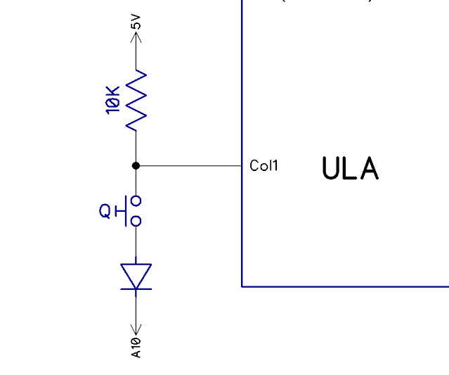
I added the pullup resistors for the "columns", they were not on the original, but I thought I would add them just in case, as they are fitted in most similar matrix keyboards. There are internal pullups as part of the input stages of the logic ICs, but it's generally not good practice to rely on them.

Since I was making one external keyboard interface, I thought I may as well make a clone of the ZX-Key. The current version was built with surface mount technology, and I really wanted to use the through hole parts in sockets so I could swap out different types of chips to see if they made a difference.

I only needed the controller board end, so I did one of those as well. Again, just a very simple layout, this was just for this testing.

The circuit for that is quite neat in that everything is done with two 74HCT245 buffer chips. This decodes A0, IORQ and RD to give the same "any even IO read" as inside the ZX81. It is a slightly odd arrangement of the diode and two resistors to create what is effectively a three input OR gate, only when IORQ, A0 and RD are low will the second 245 be enabled. I would have expected two diodes from the A6 and A7 pins and a pullup to 5V. Normally that will float high and only go low when IORQ is low and so the buffers are on, and both the A6 and A7 output pins are low. It may have been done like that for timing reasons?

The rows and columns are as before using reverse biased diodes and pullup resistors.

The diodes are at the keyboard end on the ZX-Key, but I put them on the controller in this case. That allowed me to use one of my Minstrel keyboards to do the testing. I made sure to fit sockets for the ICs as I planned to try out 74HC, 74HCT and 74LS chips (based on my theory of what was going on).
ZX81 Testing

I thought I should start with a ZX81 to make sure these keyboard worked, and indeed, both interfaces performed perfectly. Both the internal and external keyboard could be used and there was no appreciable difference between them.
Minstrel 3

I tried both keyboards with the Minstrel 3, and neither of them worked. I knew interfaces were OK, having tested them with the ZX81, so what was going on?
My theory was that it was down to the difference between the 74LS series circuits used in the ZX81 era and the 74HC series chips on the Minstrel 3.

A very simplified view of a TTL output stage is shown here. TTL uses two transistor elements. For a 0, the bottom transistor is turned on, and pulls the output to 0V. For a 1, the top transistor is turned on, and the output is pulled to the 5V rail via a resistor, usually a few hundred ohms. A Logic 0 is close to ground, where as the logic 1 is around 2V upwards in TTL land.

CMOS circuits, such as the 74HC series, use a totem pole arrangement of two FETs, one can pull direct to 0V for a 0 as before, but the other can pull direct to 5V (without a resistor). This gives cleaner, faster, lower power circuits, without having to rely on pullup resistors. This leads to the symmetrical arrangement with the centre point at 2.5V.
The problem comes if you happen to end up with two circuits driving in parallel. This is never recommended, and usually only happens unintentionally when there is a fault in the controlling logic.

In the ZX80 and ZX81, this sort of happens by design. The ZX80 was designed with a split databus, with each of the databus lines joined from one side to the other via 1K resistors. On one side, the Z80, the NOP generator and the 74LS365 keyboard buffer sit. On the other side is the ROM and the RAM and the expansion bus. This allows Z80 to be tricked into reading NOP instructions whilst the other side of the databus is reading character address / font data from the RAM and ROM.
One side effect of that is that the external keyboard sits on the other side of the resistors to the Z80 and the 365.
When HC chips are used, you get something like this:

The transistors on the right are controlled from the internal keyboard, and drive the input on the right. The external keyboard drivers are on the left, and in between is the resistor. It doesn't matter what the drivers on the left do, as the ones on the other side of the resistor will be pulling the input high or low directly. Thus the external keyboard signals will get ignored.
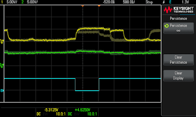
Time for some scope traces, using the Keysight EDUX1002G again. (thank you Keysight, it is proving very useful).

The yellow trace shows the D2 data line, measured at the Z80 side. The green trace shows D2 at the external keyboard side. Although this is a two channel scope, the external trigger input can be used as a third channel. It is digital only, but is ideal here to show when the keyboard is being read. Sadly it can't be used when it's not actively being the trigger, which is a bit of a shame.
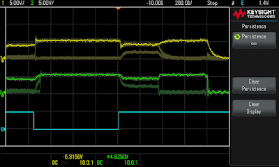
I have used persistence to show the normal trace (the thicker line with bright bits), and the duller line below was when the "3" key was pressed and the Z80 side went low and a "3" was put onto the screen. Here the green trace is unchanged because the HC245 chip at the external end was keeping that pulled high as there were no keys pressed on the external keyboard.
When the situation is reversed, it is as predicted. The green external trace shows the keypress, but the Z80 side does not register it and "3" does not appear on the screen. Do not pass go. Do not collect £200.
OK, that has proved that is doesn't work, and why it doesn't work, but what can be done about it?
Minstrel 2
My initial thought was that using 74LS TTL chips would resolve this, the pulldown resistor externally would be able to overcome the internal pullup resistor, even with the bus resistor in between. This works with the ZX81, so the ZX80 should be the same. Right?

To test that, I used the MT10 keyboard clone and a Minstrel 2. That is two 74LS365 chips with a resistor between them.

Well, so much for the theory, that didn't work.

Looking at the datasheet, it appears that the 74LS365 is a bus driver, it so has lower output resistance, 50Ω nominal. When you look at the circuit with the values in, it is clear why it is no better than the HC version.

You end up with a potential divider with 50Ω and 1KΩ resistors, which means the output is still 95% a logic 1 and only 5% logic 0. (note the ZX81 has 470Ω instead of 1KΩ resistors, I tried decreasing the resistance temporarily, but it didn't make a difference)

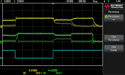
Here again, the green trace shows it dipped low but the yellow trace at the Z80 side was unmoved.

For completeness here, I also tested the ZX Key with the Minstrel 2. As expected, that did not work, even with the stronger 74HC drivers at the keyboard end. I believe the same would be true of an actual ZX80, but that is yet to be confirmed.
Here you can actually see the external 74HC driver chip is partly pulling the data line down, you can see it is only going down to about 3.5V, still well above the threshold to be read as a logic 1.
Further testing with various combinations of the Minstrel 2 and Minstrel 3 with the MT10 and ZX Key clones, with 74LS, 74HC and 74HCT chips, all failed to register keypresses from the external keyboard.

The only way I got the external keypresses to register was to remove the LS365 from the Minstrel 2, so the only player in the game was the external one. That would be an option, but that chip is also used to read from the ear socket, so it stops tape loading working. There is a spare pin on the 74HC245 on the ZX-Key that could recreate the "ear" functionality, but it wouldn't be ideal. (The NTSC signal is also read from the same address, that is done via a diode direct to the D6 line).
Solutions
Well, it seems there is not going to be an easy way of making an external keyboard work via the edge connection.

David Stephenson has created a board which plugs into the internal keyboard connector and allows a user to connect the ZX Key external keyboard that way.

Pictures again from their site - https://www.zx81keyboardadventure.com/2020/01/zx-key-minstrel-3-keyboard-adapter.html
I have looked at ways to redesign the circuit, if I was do to any Minstrels again, and I don't have an easy solution that wouldn't need a redesign with some extra parts.
One option would be to change the internal keyboard driver. It seems the ZX81 ULA must be using open collector drives on the databus, or at least drivers with much weaker pullups.
Rather than driving the databus directly, I could drive a 74LS07 chip which would the pull the databus low when a key was pressed, but otherwise would do nothing. The inputs to the 74LS07 would need pullup resistors to keep them in the "1" state the rest of the time.

It would be a little difficult to justify adding another chip and six resistors to what is already a very busy board, particularly given this is only going to affect a few people.
A simpler option would be to fit diodes on the outputs of the 74LS365, which might be more viable, so they will only pull down on the databus lines. But again, there is really no space to add those, and it is going to be of limited benefit.

Aside - Minstrel 4th
A small addendum to this story is the Minstrel 4th with Shiela Dixon's external keyboard.

Here, the story is slightly different. There is no bus split, and there is a 74HC gate and one side, and a 74LVC gate at the other side, both of which are CMOS totem pole push pull outputs.

In theory, this hits the problem described previously. However, in practice it seems to cope. The pulses are short enough that it doesn't seem to be a problem.

I did quite a few tests and there is something odd going on with the shift key, it may be implemented differently on the USB keyboard interface, possibly pressed alternately with the key rather than at the same time, but either way it seems to work.

I was planning to also look at what could be changed on the 4th to better suit using it with an external keyboard. I did look at changing to using a 74LS365 rather than 74HC365, but if anything that made it worse.

I think will leave that alone.
Second Aside - Minstrel 5
I did have something to create keypresses from an external source on the Minstrel 5, but was able to implement that on the internal keyboard matrix side, rather than having to address IO decoding and bus contention issues.
I did have to make special exception for the shift key with an extra chip just to deal with that.

That may be getting a revisit. I don't think we can do the fully fledged "thing that is not going to be called the Minstrel 5", but we are looking at the options of seeing what will effectively be "the best kit we can do with the bits that we can actually get".
Third Aside - 74x365/367
The 74x365 and 74x367 chips are very similar. Both have six buffers controlled by two pins. On the 365 (used on the ZX80), both lines need to be low to enable all six buffers. On the 367 (used on the Jupiter Ace), one pin controls 4 of the buffers, and the other control the other 2 buffers. (also shows 366 and 368 which are the same but invert the signals)

In both machines, both of the control pins are tied together, sothe 365 and 367 can be used interchangeably, I may have used the wrong number in the about post on one or two occasions. You can't however use a 265 or 267 which for some reason I keep typing by mistake.
Fourth Aside - Further Incompetence

Also note on one or both of those keyboard test boards I may have got the row and/or the column connectors in the reverse order. Doesn't really matter, it was just for the purposes of testing, so ignore any pictures where I might have switched the connections around since that last one.
Advertisements
https://www.patreon.com/tynemouthsoftware