This is an old post, preserved for reference.
The products and services mentioned within are no longer available.
As part of the multiway programmer for the
DivMMC Future programmer for
The Future Was 8 Bit, we needed a number of Spectrum boards.
The Grey Spectrum 128K +2 was chosen as these are fairly plentiful, and offer all the things required for the programmer, in a fairly compact format.
To put together a rack like that, you don't want to be taking mint Spectrums out of their tube and pulling them apart, so time to have a look through the 'broken' pile and try to resurrect some boards.
Standby for a bumper blog post.
Overview
Before I start, here is an example of a complete, working +2, time for a quick tour. First off, these are referred to as 'Greys' because they came in a grey case. Not be to confused with the later +2A and +2B which came in a black case and had very different boards inside.
This is the issue 3 version of the board. Much the same as the issue 1, with a few issue fixed and more introduced. They are a repackaged version of the 'Toastrack' Spectrum 128K, with the addition of the built in 'datacorder' cassette player and the two (non standard) joystick ports.

The three chips on the top right are the ROM, (Amstrad part number 40054). This is a 32K ROM chip, the lower 16K of which is the same as the 48K Spectrum ROM (apart from the Amstrad copyright message and a rew relocated routines because of that). The upper half is the 128K version of BASIC. The pinout is the same as a standard 27C256 EPROM. Next is the Z80 CPU, they were mainly using original Zilog parts on the +2. The last is the upper RAM multiplexor (Amstrad part number 40058), the same part as the PCF1306P / ZX8401 introduced in the issue 5 48K Spectrum, and also used on the 6A Spectrum and the 128K Toastrack. This is basically four 74LS157 style multiplexors and some glue logic. It replaced 6 chips in the Issue 4 and earlier Spectrums. Finally of note is a PLD chip, maked HAL10H8 (Amstrad 40061). This is some glue logic for the bank switching etc. This can be replaced by a GAL16V8 style chip, such as an ATF16V8 with appropriate programming. (
more infomtion here, including an updated version with some bugfixes).
The 128K has two sets of eight 4164 DRAM chips, giving 64K each. This is split into 8 banks of 16K. The top set (labelled in green) form banks 0,2,4 and 6. The lower bank (labelled in red) form banks 1,3,5 and 7. Note the chips run in different orders, with D0 and D7 at opposite ends. Bank 5 replaces the lower 16K of RAM in 16K and 48K Spectrums, this is 'contended' RAM using by both the CPU and the screen RAM, so banks 1,3 and 7 are also slower and the uncontended banks in the top set of chips.
Some of the diagnostic tools give fault reports based on the 48K Spectrum IC numbers, so the upper set, IC17-IC24 map to IC15-IC22 on a 48K Spectrum, and the lower set, IC25-IC32, map to IC13-IC6 (note reverse order).
The left hand side of the board contains the audio visual side of things, I won't be going into that much further, other than to say check TR4,5 and 7, just below and to the right of the modulator. The design appears to change from BC237 to 2N3094 at some point, but some boards have 2N3094s fitted where a BC237 should be. The 2N3904 has a reversed pinout, so should be fitted the opposite way around to the silkscreen outline. If fitted incorrectly, it can give poor composite video output.
(TR4 before and after photos thanks to @chris_jh)
The AY-3-8912A provides 3 channels of audio effects in addition to the standard Spectrum ULA audio. As with all of the 128K range, the level mixing of these four sources is not well balanced, and ULA sounds are usually much louder. The AY chip also provided bit banged serial IO. The TEA2000 is the colour encoder, and the Amstrad 40057 is the dual joystick port IO chip.
Here are a selection of boards that should be able to be patched up to do the job. I numbered them as I took them out of the box, to keep track of things.
Board 1
Board 1 appears to have become a spares board. The ULA, ROM, RAM and CPU have been removed from sockets. The RAM multiplexor and power socket have been desoldered and the lid of the modulator has been nicked.
First step is to repopulate the missing bits. With all of those back, we've got a working machine. Or at least so it seems. It seems to work for a while, and then fail, sometimes with an intermittent error usually on line D4 on the lower RAM (IC28 for those of you following along at home).
It had run several tests successfully before this one, and then after this failed. This repeats if you leave it to cool down for a while. Nothing is getting particularly warm though.
After a while, it just goes to a state where it shows this half white half black screen. I've checked all the connections as far as I can see, and replaced all the relevant parts with multiple known working parts, and still it seems to start OK then deteriorate each time it is powered on. I think there may be some unseen damage to the board, or hairline cracks somewhere, or a bad connection triggered by thermal expansion. Unfortunately I think this one is going back into the 'broken' pile.
Board 2
Board 2 is fairly intact. The RAM multiplexor has been removed and socketed, as have several RAM chips. The ROM is missing. There is a ULA present (the only one in this pile), but is missing the heatsink. Lets hope we have better luck with this one. Again first step is to insert working parts to fill the gaps.
I am swapping between two test ROMs here, both burned to 27C256R chips and fitted in the system ROM socket. Firstly
Brendan Alford 's ZX Diag V1.28. This is good at testing the lower 16K RAM, and does well to indicate the problem even with the faulty display RAM. It doesn't test the full 128K RAM unless you go through the menu, and I don't have a keyboard connected at this stage.
Here there were several RAM faults. The screen cycles around and you can usually make out the message, even though the screen RAM is faulty, it also gives several beeps to indicate the good or bad bits. Here it is saying bits D2 and D7 faulty, also indicated by the red bars on the side. It gives the IC numbers for a 48K Spectrum (IC8 and IC13). Translating those to IC30 and IC25 on this board, I swapped those chips out.
It later indicated a further error with D4 (IC28), which I also swapped out, and that passed all initial tests on ZX Diag. With the lower RAM working, I switched to
Paul Farrow's 128K RAM tester. This retests the lower RAM and also tests all the banks of RAM on the 128K.
No faults here, all looking good. I fitted a heatsink to the ULA since it was missing the original Amstrad clip on heatsink, and left it soak testing for a while, occasionally resetting it to restart the test.
Time to test with the DivMMC future to load some further test software. This initially failed as the edge connector was dirty. A quick rub over with some contact cleaner and a fibreglass pencil and it's gleaming again.
Back to the DivMMC future and it loads fine. Now running the
tape version of ZX Diagnostics (loaded from SD card), which will test ROM and system RAM (and other things if you hold down keys - see the link above for full instructions). That ran a soak test for a while and didn't detect any faults.
Important tests like JetPac and the 128K version Spellboard also passed. So that's one success.
Board 3
Board 3 is also fairly intact. The ULA and modulator lid are missing. The board appears to have been 're-capped' at some point as all the capacitors look new. The coil looks to be damaged, but it turned out to just be the heatshrink covering that had come off.
The RAM is all socketed, and only one is missing. There is a mixture of 12ns and 15ns A and B parts which is not ideal (and the one which is missing won't help much either).
When testing, I am using a current limited bench power supply, set to 1.5A maximum. That should be enough, a working +2 seems to vary between 800mA and 1.2A depending on the type of RAM chips.
This board went into current limiting straight away, the ROM and several of the RAM chips were getting hot. I removed the hottest and it took a couple of goes to get three bad chips that were apparently shorting out the 5V rail. I filled the gaps with some matching RAM and tried again.
This is doing the same black and white thing as board 1. Tried with two sets of working parts, but to no avail. Seems to be some kind of addressing issue, but all the parts which do the addressing were swapped with known working parts, which worked fine on other boards?
The RAM test also seems to pass, you can see the eight green bars down the side. I am putting this one to the side as well, but stealing the remaining working RAM chips for the other boards.
Board 4
Board 4 was only missing the CPU and ULA, and one RAM chip had been socketed. The most complete board so far. So far, it is the most complete board, lets see if that continues.
On power up, it was drawing lots of power, I had to nudge the limit up to 1.6A to stop it limiting, several chips very warm, lots of RAM faults detected. Given 5 of 8 had failed, I decided to replace the whole bank.
I also replaced one of the transistors in the power section which had been replaced with a part with a lower current rating. I fitted a ZTX651, which is the same as the ZXT650 normally fitted, just with a higher voltage rating. The original ZTX213 was still present, so I left that alone. These transistors form a similar power circuit to that used on the 48K Spectrum to provide the +/- 12V for the RAM. Here it is used for video output and the psuedo RS232 drivers.
That passed the lower RAM tests, but lots of faults were detected in the upper bank as well. I ended up socketing and replacing all the RAM.
I fitted a ZIF socket on one of the lower RAM sockets and went through all the chips from the previous boards, retesting all the removed ones, the desoldered (presumably faulty) one, and retesting my test chips.
The Spectrum Test ROM is great for this because you get an immediate indication of the state of the lower RAM on the first image. When there are lines through it, like this, you've got a problem.
Out of that I just about managed to get a set of 16 matching KM4164B-15 chips, and another working Spectrum 128.
Another dirty edge connector cleaned and the DivMMC was up and running. You can see the marks from where something was plugged in over a long period of time.
That passed all the tests and was left on soak.
Another Spectrum 128K back in action.
Board 5
Board 5 is missing only the CPU and ULA, so does that bode well based on how board 4 turned out? At first it did nothing, which turned out to be a bad power connector. With that replaced (or rather temporarily bypassed), I can test the rest. That's bound to be OK, right?
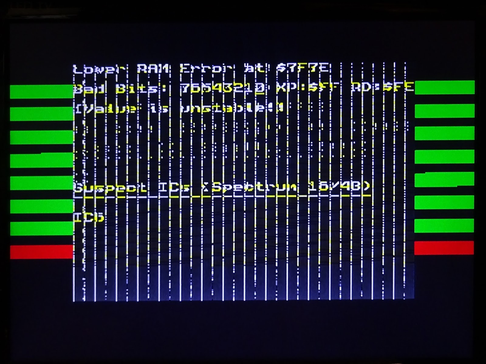
Initial testing showed a few errors, starting with D0 on the lower RAM. The RAM faults then continued to multiply on soak testing, failing one after another. This board has KM4164B-12 parts, 12nS access time rather than -15 as the others. I've matched those were possible, but had to switch to 10nS parts for the upper bank.
At this point, I have run out of RAM chips, 16 pin sockets and patience. This probably needs all the RAM removing, sockets fitting and a full new set of RAM.
Conclusion
The results of this is 34 faulty RAM chips (and plus another dozen still on board 5) and one bad ROM chip. History does not recall whether the parts originally missing were removed as they were faulty awaiting replacements or more likely removed working as the rest of the board was deemed faulty. These boards all date to mid 1986, and all the failed RAM chips are Korean made Samsung KM4164B. Is this just a bad batch that start to fail after only thirty years?
All Spectrums are broken. If you're Spectrum is broken, don't send it to me. If you want your Spectrum repaired, I suggest you sent it to
Mutant Caterpillar.