
Continuing with some extracts from of the Patreon exclusive posts during the development of the Minstrel 4D.
One of the features of the Minstrel 4D that has invited the most questions is the auto typing.
This is where the microcontroller is able to "press" keys to type onto the screen. This came about when I was working on the Minstrel 5 (that's a story for another day). I was looking into options for an SD card storage system.
Most of these involve placing a device, usually a microcontroller, onto the bus and having some code run to extend the original system to support accessing the disk drive.
I got thinking about an alternative which wouldn't require modifying the base system at all, and instead replicates the user typing the load command and pressing play on a cassette recorder.

I got quite far down the line with that on the Minstrel 5, so when the opportunity to do a 4 ½ came along, it seemed like a good opportunity to use that work.
The initial prototype of the 4D used a similar circuit to the 5. It is probably easier to start here and go onto the final version later on.
I will in fact start much earlier, with the basics of this sort of keyboard, I have written a few posts on those, so you can have a look at them if you like
http://blog.tynemouthsoftware.co.uk/2022/05/sinclair-5x8-keyboards.html
The basic premise is a 5 bit input port at address 0xFE. The inputs are all pulled high via resistors, so it will normally read as all ones.

When the keyboard is being scanned, the upper address bus is set so that one of A8-A15 is low at amy time, and each of those is connected to the rows of the keyboard via diodes. The 5 input ports create a keyboard matrix of 5x8 with these lines.
If a key is pressed, and the associated address line is low, current flows through the resistor, through the switch, through the diode and down to the address line. This makes the input of the IO port low and so a zero if read.
In order to replicate that, you can use something like a 4066. This contains 4 individual logic controlled switches which will bridge the two contacts when enabled, doing the same job as the mechanical keyboard switch, but using FETs.

That would mean you would need 40 switches, so 10 of those 4066s to control the whole keyboard, which is not ideal, plus 40 outputs to control each of those.
Thinking about other ways to do this, it became clear that some characters would need shift and another key or symbol shift and another key, so I would need to be able to press two keys at once.
I'll look at the shift keys first as that is easier as it is two keys on a single row.

In order to "press" shift or symbol shift, I am using a 74HC574, a latch with tri-state outputs. The outputs are controlled by an OR gate.
When a key is to be pressed, the address of the key on the row is latched into the 574, with the active key being low and the others high.
If the auto typing (here labelled as "fake keyboard") is enabled, and A8 is low, then the outputs of the 574 are enabled.
The diodes block a high signal from the keyboard but will allow the keyboard column line to be pulled low if the latched key was low. This gives the same result as if the mechanical key on the keyboard had been pressed.
Pressing one of the rest of the keys is essentially the same as for the shift modifier keys, but now has diodes connected to all five columns.

Only a single row needs to be selected, so that can be set using a three to eight decoder, a 74HC251.

Here the row is set by the three output (Fake_KB0-2) and that controls the selection of A8-A15 (arranged in the order of the keyboard connector), which is used to control the 574 latch.
The procedure is then:
- Latch modifiers first 574
- Latch key into second 574
- Set row address on 251
- Set keyboard enable
- Wait long enough for the key to be registered
- Release keyboard enable
- (no need to reset anything else as they will not be activated if enable is high).
That was the version as implemented on the first Minstrel 4D prototype.

That all works very well, but was using up a few too many pins on the microcontroller, so I came up with a cunning plan and replaced the 574 latches with 595 serial latches.
These do a similar job, but rather than setting 8 bits and then clocking them in once, you set one bit, clock it in, set the second bit, clock that in and so on.
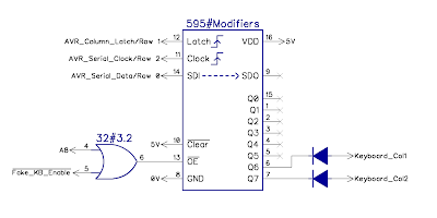
As before, there is one for the modifiers, and one for the rest of the keys.

Normally, the 595s would be chained together, so the data passes through each chip until all the bits required have been clocked in, then all chips are latched at the same time. In this case, I have run them in parallel. I only need 5 bits for the key and 2 for the modifier, so that means I only need to clock out a single byte to set both latches at the same time. (I need to separate chips as their enables are different)
The Row address is set on the 251 as before.

Once the clock and data latches have been used to latch in the column positions, the same lines can be reused as the row selections. The only caveat is the line which drives clock is left high, and can be set low if required, just as long as there is no low to high transitions as that would trigger the clock.
I tried this out using my usual subtle, almost invisible, modification techniques.

The next version was somewhat neater (on the final version, I turned all the diodes around so they matched the ones on the rest of the board).

Using something like a 595 shift register is of course slower as you have to clock in 8 bits of data, but in this instance, speed is not important.

Automatically loading TUTTUT takes about 35 seconds, about 3 seconds of which is typing.

Setting a keys takes less than 10uS.

Once pressed, I have to wait over 100mS to be sure they key has been read, and another 25mS before pressing another one.

These times vary, because the delay takes into account how often the key is being read - as indicated by the IO_FE_RD signal. (I later updated the code to count IO_FE_RD pulses to know when they key should have been read)
So that is the auto typing.
I started with it typing "LOAD TUTTUT", then waiting until it had loaded and then typing "TUTTUT" to run the program, but it sometimes missed the first character or two, depending on how long it takes to process the loaded file before checking the keyboard again.

To get around that, I set it to type "LOAD TUTTUT TUTTUT" at the start. It plays the file into the ear pin and the games loads. Since the load operation only took "LOAD TUTTUT" out of the keyboard buffer, "TUTTUT" is still left there and once it is loaded, it goes back to the input buffer and reads that, which runs the game.

This mechanism is also used to load the menu program. "LOAD menu menu" is typed at the start and the brief menu program is loaded. Having lots of pages of text in the menu program took too long to load, so to speed this up, the menu program only does two things.
- It displays whatever text is sent to it
- It sends back any keys the user presses
The microcontroller generates the menu pages, sends them over the "sort of rubbish spi" (see the previous post on that http://blog.tynemouthsoftware.co.uk/2023/02/minstrel-4d-development-part-2.html).
The menu program running on the Z80 displays the page and waits for the user to press a key. When it gets a keypress, it send that back to the microcontroller (also over SPI). The microcontroller can then send back another page of menu, or carry out the requested action, read the SD or start the loading process, or whatever was requested.

During testing, I had this wired up so that it typed out whatever you sent over the serial port. Since that seemed useful, I left that in, and have been using it a lot for testing. See the previous post on some Forth coding examples - http://blog.tynemouthsoftware.co.uk/2023/01/some-simple-forth-programs-for-minstrel-4D.html
I also added the option to read a .txt or .fs file from the SD card and type that in directly. It takes a while, but it's a lot easier than typing it in yourself.

Advertisements
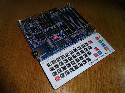
Minstrel 4D
The Minstrel 4D kits are shipping now, you can order one from The Future Was 8 bit - SPECIAL OFFER - £15 off the Minstrel 4D and free shipping to the USA
https://www.thefuturewas8bit.com/minstrel4d.html
More info in a previous post:
http://blog.tynemouthsoftware.co.uk/2022/08/minstrel-4d-overview.html
Patreon
You can support me via Patreon, and get access to advance previews and behind the scenes updates. These are often in more detail than I can fit in here, this post contains bits from several Patreon posts. This also includes access to my Patreon only Discord server for even more regular updates.
https://www.patreon.com/tynemouthsoftware
