Sunday, 11 September 2022

Tut-Tut for the Commodore PET

This is one of those occasions where I go to find a link for someone to an old blog post, there isn't one. This one I wrote for Patreon, but had not moved it over to the blog, so now I have.

The PET remake of 3D Monster Maze seemed to have gone well (although it hadn't been released yet), so I thought I would have a go at another favourite game.

Tut-Tut started life as a type in BASIC program for the ZX Spectrum, by David Stephenson, published in Paleotronic magazine in November 2019.

https://paleotronic.com/2019/11/05/tut-tut-a-new-game-for-the-zx-spectrum/

This version has most of the features, but being written in BASIC is a bit slower compared to later versions, particularly when drawing the screen.

This was then expanded by David to a full ZX81 game, released on tape by Cronosoft.

This did well to make use of the ZX81 character set, and added more levels to the mix. It ran much faster as it had been written in C.

This was followed by a fuller Spectrum version. This time in a complied version of Spectrum BASIC. This added sound and joystick support and more levels.

Next came a version for the Jupiter Ace / Minstrel 4th, but not this time by David Stephenson, but by George Beckett. This was written in Forth (as is customary on the Ace), and was the first (and so far only) commercial game released for the Minstrel 4th.

So, it's a great game and seems suited to the type of machine I like to work on. The PET version couldn't use user define graphics like the Ace and Spectrum versions, but it did have (almost) all of the characters used on the ZX81.

Not as problematic as the missing half black half grey tiles that let to the remapping of the screen on 3D Monster Maze, but just the lack of a £ symbol.

It's an odd thing because there is no £ symbol on the PET, even the later 80 column business version with a different keyboard did not get a £ sign. Seems a bit lacking for a dedicated business machine. And yet the low end games machine that followed a few years later, the VIC 20, not only had a £ sign (replacing the \ on the PET), but it had a dedicated key for it. You had to press shift + 4 for a $ sign, but £ had it's own key. Never understood why.

The PET did have some extra characters, including playing card symbols. The clubs symbol (♣) seemed a good choice for the Ankh amulet, so I used that.

Behind the scenes, the code required some work to compile for the 6502. It had been written in C and used lots of 16 bit integers and arrays of arrays of structures. This was all a bit much for the poor 6502 with no 16 bit registers and no 16 bit commands, so I rewrote a lot of that code to use 8 bit bytes and simplified the memory structures to result in less pointer arithmetic.

Even though the PET's 6502 running at 1Mhz is less than one third of the 3.25MHz Z80 in the ZX81, it sort of balances out as many of the Z80 instructions require quite a lot of cycles where the 6502 most are one or two.

Even after all that, like most games of this type, most of the time is actually spent it loops waiting to redraw the screen or for the player to move.

Movement was a bit of an issue as I originally used the cgetch() routines in the gcc complier to read the keyboard. These do not support key repeat, so there was a lot of keypresses to move from one side of the screen to the other. I ended up writing a new keyboard scanning routine, so you could move by holding the key down as you would expect.

The PET screen is 40 characters wide, the ZX81 32 characters, and the Tut-Tut levels 24 characters. I wanted to maintain the level data from the ZX81 version, I could have adapted it, but I didn't want to risk breaking some of the later levels that I didn't actually know how to complete.

The easiest option was the one I chose, padding the screen with four blank characters at each side and otherwise following the ZX81 screen layout. That led to a few interesting issues such as the starting positions of the player and the mummies which is calculated as the offset in the ZX81 display file from the top left character in the playfield. The ZX81 display file includes a newline character at the end of each line, so it is 32 characters + newline for each line, 33 bytes per line. I had to convert that to a position in the PET display which is 40 characters per line, with no newline character.

The 33 bytes per line issues also affected the animated player and mummy graphics as the characters used were alternated based on the low bit of the horizontal position when moving left and right, so they alternated as the player moved along the line. Vertically, this also alternated with 33 characters per line, but with 40 characters per line, it was always the same, so an artificial wiggle needed to be added when moving up or down.

I took a few features from the fuller Spectrum implementation, including sound and the  pause feature (I was particularly proud of the pause graphics for some reason). The sound was written for the Spectrum using it's BEEP routine to play a tune which was almost, but not quite, entirely unlike "Walk like an Egyptian" by the Bangles.

In order to play the tune, I did a lot of research into the musical abilities of the PET. I didn't find much, so I worked it out and wrote it up here:

http://blog.tynemouthsoftware.co.uk/2022/05/pet-sounds.html

The game was starting to come together. Time to add the title screen

I kept the credits on the title screen, which included a nod to Rod Bell (Villordsutch). I couldn't resist adding a similar line for The Future Was 8 bit's Rod Hull.

That seemed a little unfair, so I added a little animation of a Mummy correcting that.

So that is Tut-Tut for the Commodore PET, available on tape from The Future Was 8 bit (cover artwork by David Stephenson)

https://www.thefuturewas8bit.com/cas024.html

And also as a digital download from my itch.io page:

https://tynemouth.itch.io/tut-tut-commodore-pet

There is a review here with links to all of the other versions on download and cassette.

https://www.zx81keyboardadventure.com/2021/08/tut-tut-on-commodore-pet.html

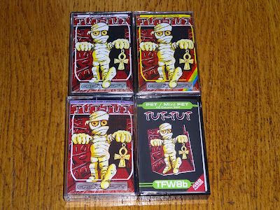
Here are the four cassette versions.

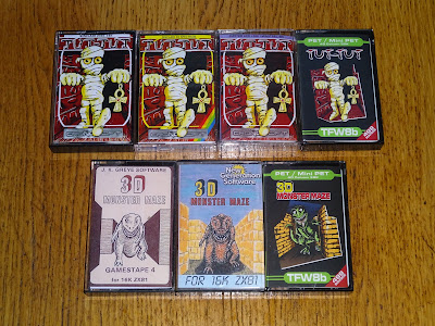
And to complete the collection, my PET remake of 3D Monster Maze alongside the two earlier release.

Advertisements

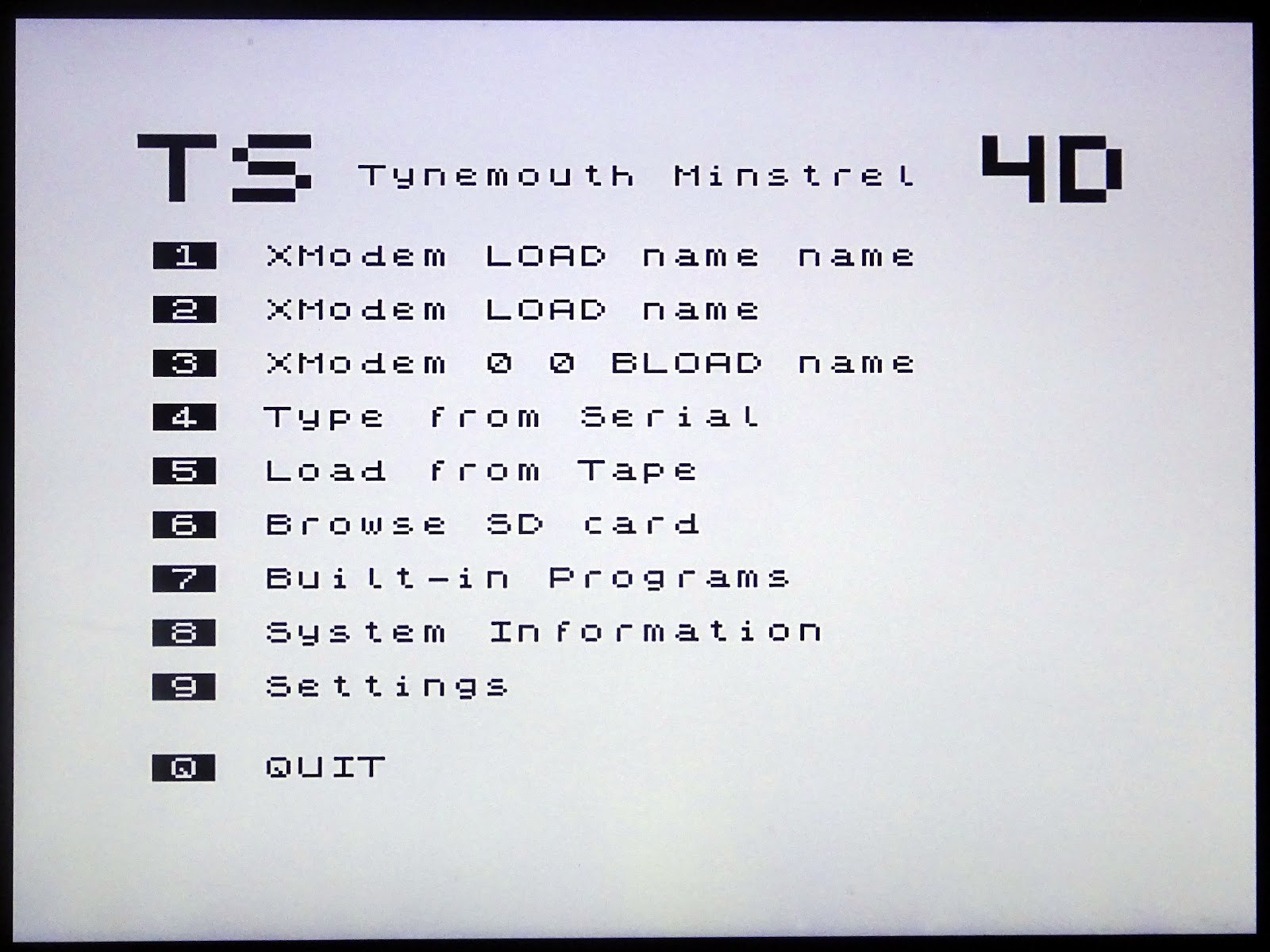
A reminder that there is a specially updated version of Tut-Tut built into the Minstrel 4D.

The Minstrel 4D is available for preorder from The Future Was 8 bit

https://www.thefuturewas8bit.com/minstrel4d.html

Patreon

You can support me via Patreon, and get access to advance previews of posts like this and behind the scenes updates. This now also includes access to my new Patreon only Discord server for even more regular updates.

https://www.patreon.com/tynemouthsoftware

Sunday, 4 September 2022

Building a Minstrel 4D Kit

The new Minstrel 4D Jupiter Ace compatible kit with SD and serial loading, joystick port, posh keyboard and RC2014 slots is available to pre-order now.

https://www.thefuturewas8bit.com/minstrel4d.html

More information on the features and specifications in a previous post here:

http://blog.tynemouthsoftware.co.uk/2022/08/minstrel-4d-overview.html

We are starting to assemble all the parts that will be going into these kits. Although some of them come in disguise. Imagine my disappointment when I found out this wasn't actually a giant Toblerone.

But instead was full of chips from TFW8b stock to use in the kits.

I have already built several Minstrel 4D boards up during development. They usually start out looking quite neat

But these usually end up with one or two modifications.

Before I roll up all those changes into a new revision and everything is neat again.

But inevitably, some more changes do creep in.

Just before we opened the pre-order, I built up one final prototype version. This, I hope, will be the final version of the PCB*.

* it won't be, I've already made several changes

I have put together a few component packs

And IC packs

So it is time to put one together.

As with any kit like this, I start with the lowest height parts, and fit all the resistors, capacitors and diodes.

You lose points if you get the diodes the wrong way around (they are all marked on the board). But you get bonus points if you get all the resistor colour codes the same way around and extra bonus points if you position the capacitors so their value can be read.

I usually pop rivet TO220 packages like the MOSFET and 7805 to the board. It's not necessary, you can solder the tabs, or use a nut and bolt, or just leave them flapping about in the breeze. The MOSFET needs no additional heatsinking, it will not got warm even at full load. The 7805 does not need a heatsink for normal 4D in use. That is about 100mA, and it's not even warm. It may need a heatsink if you use a lot of expansion cards. Whatever you do, don't connect the tabs together electrically as the 7805 is 0V and the MOSFET is at 9V.

The kit will come with the SD socket presoldered, as they can be a little tricky. I guess that will be me soldering a massive pile of SD sockets then.

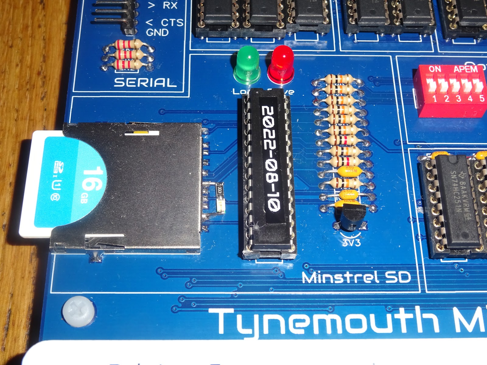
Just jumping ahead here, one slight change that happened in the last few days is the addition of a third LED there to show SD access. It fits in there so perfectly that I had to do it.

I was just going to flash the other LEDs, but it has been useful to see the SD access separately.

My development board has this LED added using "surface mounted" components.

For this preview build, I used an actual surface mount LED and resistor soldered directly to the socket, which although still a bodge, is a bit neater. (I did think about drilling two holes in the PCB, gluing the LED in place and wiring it on the back of the board, but there seemed a lot of opportunity to totally screw things up that way)

Back to the build, and next come the IC sockets and connectors. Points off if they are not level or the notch is the wrong way around. Here I have fitted sockets for all the ICs, so I can test batches of chips as I pack the kits. The actual kits will only come with sockets for the microcontrollers, ROM, RAM and Z80. You can fit extra sockets yourself if you like, but I think it looks better without them.

The expansion bus connectors at the side have been spaced so you can hold them in place with some pin headers inserted into the sockets to keep them vertical during soldering.

Next, it's time for the ICs. You can at this point try powering it up and see if there is 9V getting in. Then add just the 4013 and 40106 and see if the 5V will turn on and off, and is present on all the sockets etc. Then you could install the video circuitry (which is self contained and isolated) and see if you get something on the screen.

Then a few more parts, checking if the clock is running etc, until you have installed all of the chips.

Or in my case, I am fairly confident (or maybe fairly arrogant, at least fairly optimistic), so I just install them all in one go.

I have fitted the four yellow key switches for power / turbo / reset / menu, just to allow me to turn it on.

And we have a beep and a menu. Success.

Before I can try any more of that out, I need to fit the rest of the switches.

And the keyboard overlay (which is where the pictures all get a bit darker because I don't know how to tell the camera not to compensate for the white PCB)

Next it is onto cutting up lots of little squares of paper for the keys themselves.

Yay, I have a computer that runs forth and a keyboard.

There is only one thing to do, isn't there.

That all seems to be working nicely.

I had spotted a mistake on the keyboard artwork, and some of the symbols were slightly out of place, so I decided to redo them all with a new template.

The colours are just to allow me to select "all the letters" or "all the symbols" etc. Although I did add a splash of colour to the function keys.

That's all built and working nicely, ready to go?

Well, I have an advantage, I designed it. I know where the bits go.

In order to test a more representative build, a second kit was sent down to TFW8b.

There was a draft manual, but Rod did a live build on youtube relying only on the board markings (and some guy in the live chat).

If you don't have three hours to spare, here is a 60 second sped up version.

A couple of things came out of that test build, and a few changes have been made to the board, including now using three 47nF capacitors, in order to make it easier to differentiate them from the two 22pF capacitors.

Think you can do it faster or better? Well order yourself a kit and film it and send us the video.

Advertisements

The Minstrel 4D is available for preorder from The Future Was 8 bit. This will be a self assembly kit, using all through hole components. These should be shipping a 2-3 month.

https://www.thefuturewas8bit.com/minstrel4d.html

Patreon

You can support me via Patreon, and get access to advance previews of posts like this and behind the scenes updates. These are often in more detail than I can fit in here - there was a whole post on the additional 47nF capacitor with oscilloscope traces and schematics and everything.

This now also includes access to my new Patreon only Discord server for even more regular updates - I was posting pictures of this build live on there.

https://www.patreon.com/tynemouthsoftware

Sunday, 28 August 2022

Testing PET ROM/RAM Boards

This is a reworking of two Patreon exclusive posts from last year. I was building a large batch of PET ROM/RAM boards for The Future Was 8 bit, and I wanted to update my test kit. I am currently building another large batch of boards, so it seemed fitting to revisit these posts.

The current design of the PET ROM/RAM board has evolved quite a bit since the first ones I produced back in 2014, but the concept is the same. Plug into the CPU socket of a PET to bypass and/or upgrade the onboard ROM and RAM.

Since this was also acting as a piece of test equipment, it was important to me that I tested each of the boards I built to make sure they were working correctly. So that the buyer can just plug the PET ROM/RAM board in and be confident it will work.

In the early days, I would test these in my 4032, although that complicated things slightly as this generation of boards drive the display with a CRT controller chip which needed to be initialised by the ROM before it would generate sync signals, so I had to remember to boot up to a 4032 or 8032 ROM image or the onboard ROM set first.

This meant the CRT had to be run all the time the board was being tested, which is not ideal, I try not to overuse nice tube based monitors for trivial tasks when a disposable LCD display would be sufficient.

I used various other boards, including a 2001N board from a 3016. That had the advantage that an adapter could be used to generate a composite video signal from it, so it didn't need the CRTC to be initialised or the CRT to be run during testing. It did however still need the big PET power supply to power the 4116 RAM chips.

When I got hold of a broken 2001 board, that became an ideal test harness.

The board originally ran from a centre tapped AC transformer, and only used the 9VDC that generated to power the datasette motor drive circuitry, everything else on the board being 5V. With a suitable cable, this could be run from a 9V DC bench supply. It did run at over 1A due to all the LS TTL logic on there. (A Mini PET for reference runs at about 100mA due to the use of HC logic).


This had several failed 6540 ROM chips (no surprise there), unfortunately including the character ROM, which is in a different circuit and cannot be replaced by the ROM/RAM board. It was also low on working 6550 RAM chips, so I put the remaining working ROM and RAM safely away and made replacements.

With the 6520 and 6522 chips replaced with WDC ones, this became a nice stable board with no MOS parts to worry about wearing out.

This could also drive a composite signal with no programming, in fact the PET's party trick is that it will still drive the display if there is no CPU installed due to the completely separate video circuitry.

Add to that an SD2PET to load test software and it's pretty much sorted.

The final element was a replacement keyboard, one of the first ones I mad, which had the nice white switches (before TFW8b insisted on those less than ideal blue ones).

The was supported on a second PCB to prevent it scratching the bench.

Most of the time, I was using a BASIC RAM test program I had adapted from one in a book or a magazine many years ago, adding bit wise testing and address bus testing.


This was  deliberately slow and deliberately written in BASIC as it means lots of ROM and RAM accesses, but did take about an hour to complete. That meant that whilst a board was on test, I could get on with labelling and packing the previous board and then cleaning, checking and programming the next one ready for test.

That has been working well for a many years, building these in small batches for my store (now at https://www.sellmyretro.com/store/tynemouth-software) but since TFW8b is now ordering these in larger quantities, I think it is time to retire the 2001 board and look for something new.

I set out a few requirements:

  • Single 9V DC supply
  • Composite video output
  • Long term reliability
  • SD card loading
  • Compact size

You might think the obvious solution would be a Mini PET. After all, they meet all the above requirements, and I might have one or two of them lying around here.

And yes, that would be an obvious choice, particularly one of the development builds that would not be saleable, such as the Mini PET Stealth created from one of the batch of PCBs with no silkscreen.

However, there is one problem. As the marking indicates, the socket on the Mini PET is not suitable for a 6502 CPU. 

The W65C02S used there has a slightly different pinout and different timing requirements to the original 6502. A couple of pins need extra pullup resistors, and one input is now an input/output pin which means it should have an inline resistor if used (which it isn't). The most notable changes though are one of the ground pins on the 6502 that has to be connected to ground is now an output on the W65C02S. Secondly, I found during development that the clock out on the W65C02S was not suitable for driving the rest of the system as it is on the PET. Instead, it has to be driven based on the input clock rather than phi1/phi2 output as on standard 6502 systems.

Before I knew the clock out was unsuitable, and how different the timing had to be, I tried on the first Mini PET to make it suitable for either type of CPU.

That is PCB V1.00, the very first Mini PET. I did get that working in the end, and it was mostly right.

As with many early prototypes, I used GAL chips for things like address decoding to allow me to change that without needing to change the PCB.

Inevitably, there are changes, as you can see, the Mini PET once had a 555 timer based reset circuit, but that function was taken on by the CRTC microcontroller to save space on the next board....

This was the second board produced, V1.21 (I was clocking through revision numbers for each change made to the design).

This one still had a few features which were eventually dropped, including selectable CPU clock. This seems like a neat idea, but in the end not. Datasette loading didn't work over 1MHz as it was asynchronous and had to match the clock timing. IEEE-488 failed over 2MHz (also due to timing based on cycle counts). Changing the speed after loading often failed due to contact bounce on the jumpers, which could have been resolved with a 157 or a 4066 or something like that, but the feature was dropped to avoid causing problems. (I did go for this on the Minstrel 4D, which now has a turbo button to switch clock speed - http://blog.tynemouthsoftware.co.uk/2022/08/minstrel-4d-overview.html)

This board had the GAL replaced by logic chips but still needed some extra mods trying to get the timing right.

This version of the board did have one important difference, I had added a jumper to select the clock source between a WDC chip or a MOS (or Rockwell etc.) standard 6502. This did not address the pin 1 ground / output pin issue, and left that pin unconnected, which some 6502 chips were not happy with, they do seem to need both pins connected.

It almost worked, but memory access timing to fit both chips was right on the edge, and would occasionally fail. I could never get it properly reliable with both CPU types, and to support both would have needed two different memory timing circuits selected based on CPU type. That would need a block of four jumpers to change CPU type. I decided that since this was going to be a kit, and going to be supplied with a W65C02S, it was best to just tune it perfectly for that and remove 6502 support - hence the warning on later boards.

I did look into building up another V1.21 PCB to use for testing, thinking I could miss out the parts I didn't need, but when I looked into it, all I could leave off were the datasette motor power circuits. Pretty much everything else was required if I was going to access the IEEE-488 bus.

There didn't seem much point in duplicating the whole thing, so this board will become the test rig. This one was already modified to 6502 timing, and with a ground wire attached to pin 1 (underneath) it was ready for use. It just needed a few extra sockets to rise above the 'vertical modifications'

It does need a keyboard. I could have used the one from the previous rig, or build another of that type, but I decided it would be better mounted to a solid board. I had a look through the scrap PCB pile, and found some boards from the Mini PET 40/80 development.

This was the first design with the build in keyboard. I had spaced the keys out wider and added the extra keys for power / reset / menu in a vertical row above the keypad. I didn't like this, so on later revisions, I went back to the closer spaced keys and had the four function keys down the right hand side instead.

With nothing populated on that board, I can use only the keyboard, via a plug and socket arrangement. I also added pillars through the boards for support, including an extra one directly under the 6502 socket for extra support.

The nice white light touch key switches I use on these are expensive, so I didn't want to allocate a full set to this. Instead, I used up some of the yellow hard touch keys we received in error one time. They aren't as nice to type on, but I am not expecting to type on this keyboard much.

In fact, the only keys I really need are Shift and Run/Stop.

The testing software is carried across from the old rig. I alternate between the old hour long BASIC test program and a shorter test using a modified version of the Mini PET self test ROM.

These are the only programs on these SD cards, so can be loaded with Shift + Run/Stop.

The display is a little bit wavy there as the CRT controller on the V1.21 Mini PET board was an early development version, and by the looks of it had a few extra instructions on the 8th line that were not being offset in the other 7 correctly. This was all fixed in later versions, but I think some of the pin allocations are different on this board, so I have just left the microcontroller on there with whatever version of code it last had as it works well enough for the RAM tests.

Add an SD2PET and the new PET ROM/RAM board test rig is ready.

I was going to wire up the soft power on circuitry on the V1.76 board, but that was an early version and it was improved in the later boards. The inline power switch works fine, so I will just stick with that.

The test procedure I normally follow is to have the onboard RAM disabled, and the onboard ROM set to something different (in this case, there is a development version of Mini PET BASIC on there. Just needs to show if it is using the onboard ROM or the replacement ROM.

I start with the PET Tester ROM which does the B/G test on the first 1K of RAM, then shows the character set and repeats. The screen of 'B' characters when no RAM is enabled really shows up the development video controller timing.

Following that, I enable the replacement RAM and it should go to G's. Then go through the ROM images, quickly checking it will boot to BASIC 1 and BASIC 2 and finally I select the CRTC BASIC 4 ROM which should boot up on any PET, I leave them set like that. Once booted, I use SHIFT+RUN/STOP to load one of the test programs and leave that running for a bit.

If I am packing a batch of these, I will run the modified Mini PET System Test and let that loop 10-20 times whilst I pack the previous board and prepare the next one.

I occasionally switch to the slower BASIC memory test if I am taking a break, and let that run through it's hour long test.

I could probably dispense with all of these tests, since every single board in the last batch passed, (full disclosure, one was rejected before testing as I noticed one pin had not been soldered, but when soldered it tested fine). I still test them all I regard these as test instruments, and want to be confident that each and every one of them is tested and working well.

Since starting to sell these via TFW8b, I have upped the game a bit, and these now come in their own little boxes, complete with their individual serial numbers.

These stack quite neatly in the larger boxes, ready to ship down to the Pink Windmill for distribution:

Advertisments

PET ROM/RAM boards are available from The Future Was 8 bit:

https://www.thefuturewas8bit.com/shop/commodore/pet/petromram.html

As is the SD2PET

https://www.thefuturewas8bit.com/sd2pet-future.html

I am a bit surprised the PET ROM/RAM boards are still very popular, I sort of expected that when we launched the Mini PET 40/80D that would have been the end for the PET ROM/RAM. The Mini PET 40/80D is a drop in replacement for any PET board, so not only fixes any problems, adds 40/80 column mode, upgrades the ROM and RAM, and adds a built in SD2PET.

https://www.thefuturewas8bit.com/shop/tynemouth-products/minipet4080d.html

Patreon

You can support me via Patreon, and get access to advance previews of posts like this and behind the scenes updates. This now also includes access to my new Patreon only Discord server for even more regular updates.

https://www.patreon.com/tynemouthsoftware