
Last week I built an RC2014 sound card, now it's time for the digital input/output board kit I ordered at the same time.

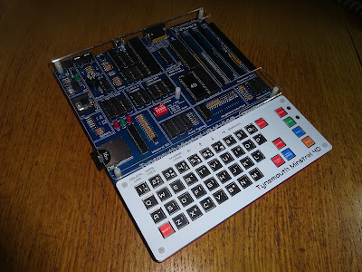
This is an RC2014 module from Mr. RC2014 himself. I built one of those with my first "full size" RC2014 system. The one before that was the "classic" low profile version (before it was called the "classic"). I also used that when testing the Minstrel 4th.

With that one, I hard-wired the address as 0x00, as it seems most people do, but I needed to do some testing at other addresses. I could have just removed the wire link and fitted some jumpers, but since I was ordering the sound card from z80kits.com, I thought I would get another kit.

Construction followed the normal practices for boards like this (other than me mumbling to myself that some of the footprints aren't quite the right size.....)
Jumpers aren't part of the kit, but I think the point of kits like these is you can make them your own way. When you are starting out, it is good to follow the instructions and build it as intended, but once you have done a lot of them, you change things to suit yourself.

I also switched out the IC sockets for my favourite turned pin ones, and the LEDs for 5mm ones just because I wanted to.
I meant to order some small, blue resistors to better fit the board, but I forgot.

Don't forget to fit the two link wires. See later for more detail as to why, for now, just remember to fit the two links.
The card has two ports, independently addressable. One 8 bit output port, 8 LEDs, latched on an IO write to the selected address 00, 01, 02 or 03.

The input port is 8 buttons, read on an IO read to the selected address, 00, 01, 02, 03 as before. They do not need to be the same address. These return 1 if the button is pressed, 0 otherwise.

I say 8 buttons, but somehow I managed to lose one along the way. I know it was there when the kit arrived as it is in the above knolled parts image, so I most have lost it on the bench somewhere. I replaced it with a similar part, but I didn't solder it. As soon as I post this blog, I will find the missing button and be able to fit it.
(as someone who sells kits, I know some kit builders would be getting in touch to complain that there was a switch missing from their kit. Always a good idea to knoll the parts out before you start to make sure they are all there, and handy to take a picture to know if you lost it or it was actually missing)
To test the card, I wrote a simple test program.
: SLOWLED
  BEGIN
    256 0
    DO
      I 0 OUT

      2000 0
      DO
      LOOP
    LOOP
    0
  UNTIL
;
You can type that in or cut and paste it over a terminal as I did in the previous post.

I ran that and the LEDs counted up in binary as intended. Nice. Who doesn't love blinkenlights?

The other thing I wanted to try with a modification George Beckett has made to his port of 3D Monster Maze for the Jupiter Ace. Or in this case, a special Minstrel 4D edition called 4D Monster Maze (because we couldn't not call it that once I had thought of it).
With this version, the LEDs act as a range detector, showing how close Rex is.
George built his IO card with address 03, so the early version of the code I was testing was writing to address 03. I changed the output port jumper on mine to address 03 to match.
I loaded up the special build and wandered about the maze and I walked straight into the exit. The one time I actually wanted find Rex I find the way out.

I tried again, and this time Rex found me as usual.

As "footsteps approaching" appears, more and more LEDs light until it reaches eight.

Then the players is ate. (sorry)

George has now published his finished version of 4D Monster Maze with the built-in Rex tracker.
https://github.com/markgbeckett/jupiter_ace/tree/master/3d_monster_maze
This has been updated to allow the user to select which IO port to use, just press R on the "Anyone there?" screen.

This is a nice addition to the game, it gives a new element to the gameplay as you now have a better indication of where "Rex Lies In Wait".
More Details
One thing that came up during testing reminded me of something I was going to mention before, so I guess I may as well add it now.

During testing George found that his card was responding to all addresses in the range on 00-03, not just the jumpered one. (photo stolen from @markgbeckett)
Can you spot the problem?

When I was building mine, I had to dig out the schematic to check what those pins marked "Link" were for. They are indeed links, and should be fitted.
The two links can to be used if you want to change the address the card uses, by breaking those links and fitting some additional circuitry. But in most cases, they should just be installed in the marked positions.

I have redrawn the schematic to highlight the relevant area:

The 74HCT138 chip is a 3-8 line decorder, which will set any one of its 8 outputs low if it is enabled and the appropriate address appears on it's input pins. (it has only just occurred to me after using these chips for nearly 40 years that the 3 and the 8 in 138 might be related to it being a 3 to 8 decoder? or that might just be coincidence?)
Here you can see the two links connect address lines A0 and A1 to pins 1 and 2 of the chip. The third address input is connected to the /WR line. This is low when a write operation occurs and high otherwise (i.e. a read operation).
You can see from the table on the diagram that for a write operation, the A2 input on the 138 will be low, so one of the /O0 through /O3 outputs will go low. Which of the four depends on the A0 and A1 lines, which are connected to the Z80 bus A0 and A1 lines via those links. One of the four possible outputs goes low, and if you have the jumper on the right in that position, it will enable the output latch chip.
For a read operation, /WR will be high, so it will be one of the bottom 4 output lines, and again is determined by the jumper.
Here I have drawn in the two links fitted, and the jumpers, set for address 0.

There are three other inputs, which all need to be in the correct state to enable the output.
E3 is connected to /M1, and is there to avoid false triggers when there is an interrupt acknowledge. The 138 outputs are only enabled if /M1 is high.
/E2 is connected to /IORQ, which is low only for IO requests, so the 138 is only active for an IO Request.
/E1 is connected to a signal which is low when an address in the range 00 to 03 is selected.
This is generated by a diode OR gate, connected to address lines A2 - A7.

If any of the inputs are high, the the address must be greater than 03, so the 138 should be disabled. When all the inputs are low, the 138 input is pulled low by the 10K resistor.
Or, in short, don't forget to fit the two link wires.
Look out for future posts where I will be testing this and the AY-3 Sound Card further in the Minstrel 4D and other RC2014 systems.
Advertisements
Minstrel 4D
The Minstrel 4D kits are shipping now, you can order one from The Future Was 8 bit
https://www.thefuturewas8bit.com/minstrel4d.html
More info in a previous post:
http://blog.tynemouthsoftware.co.uk/2022/08/minstrel-4d-overview.html
Z80 Kits
The RC2014 Digital IO Module is available from Z80Kits.com
https://z80kits.com/shop/digital-i-o-module/

Patreon
You can support me via Patreon, and get access to advance previews and behind the scenes updates. These are often in more detail than I can fit in here. This now includes access to my Patreon only Discord server for even more regular updates.
https://www.patreon.com/tynemouthsoftware
