
My Patreon supporters have had this for a while, but I have been holding off posting it until the Minstrel 2 and 3 kits were back in stock, in case any of you wanted to build your own to follow along.
The ZX80 is quite an amazingly simple design. One of the impressive things is the way the it generates a video signal without a custom video chip, or any of the counters and comparators normally required for a logic implementation.
It does this at the expense of performance and the user experience.
The ZX80 display operates in two modes:
- The Z80 is devoted to drawing the screen. No user code is run, and the only non-screen drawing activity is scanning the keyboard
- When a key press is detected, it switches into code running mode (later called Fast mode). Here the Z80 is running code, and the screen is not drawn.
For short bits of code, such as typing in a character as a part of a BASIC program, this will be a brief flash and as soon as the typed letter has been processed, the display drawing will then resume.
For longer bits of code, such as pressing newline to complete a line of code, this takes a few seconds. The longer the program, the longer the delay adding each line.
And finally, for running code, this can be an extended period where the screen is not being drawn, and so the TV will just show snow (or a modern TV will drop to "No Signal").
Players of 3D Monster Maze will know this as "the mists of time".

This occurs when the maze generation code is being run and the screen is just snow for 30 seconds as some BASIC code generates the maze. In my remakes of 3DMM this section is written in assembler and takes less than a second. I added a "snow effect" of clearing the screen, which actually takes longer than the maze generation code, which is run whilst the user is reading the "mists of time" message.
So, how does the ZX80 achieve screen drawing with relatively few parts?
Vertical Sync Timing
First, lets look at the vertical sync. This is a regular pulse every 20mS of around 384uS. That is a frequency of 50Hz for the UK model. The USA model produces vertical sync pulses every 16.7ms (60Hz).

This is controlled in software. the exact frequency depends on the number of lines, which is set by a the presence of a diode on the ZX80. On ZX80 USA models (left), there is a diode fitted at D11, on the standard UK model (right), it is omitted.

On the Minstrel 2, the diode is always fitted, but is taken out of circuit if the jumper is set to PAL.

This is about as simple as an I/O port can get. If the diode is in circuit, then when the keyboard port is read, /Keyboard goes low, and current flows through the diode, pulling D6 low and that bit is read as 0. If the diode is not in circuit, it is read as a 1 (it is loosely pulled up through the D6-D6' 1K resistor and the 47K pull up on D6').
The PAL/NTSC setting is read each cycle and used to determine how many lines padding should be above and below the text area. NTSC models have 32 lines added at the top and bottom of the screen. UK models have 56 lines are added.
The vertical sync section is around 384us, which is 6 lines at 64us each.
The text area of the screen is 24 lines of 8 x 8 characters, so 192 text lines in total.
Section |
UK / PAL / 50Hz |
USA / NTSC / 60Hz |
Vertical Sync |
6 |
6 |
Top Border |
56 |
32 |
Text Area |
192 |
192 |
Bottom Border |
56 |
32 |
Total |
310 |
262 |
Ideal |
312.5 |
262.5 |
(I am jumping around a bit in terminology, I will try to stick with UK and USA models rather than PAL or NTSC, since there is no colour component to the signal and the difference is the refresh rate)
The UK models produce 310 lines per frame, and USA models produce a total of 262 lines. These are repeated identically for odd and even frames, giving a 620 and 524 lines when interlaced (close enough the the ideal 625 / 525 lines).
Vertical Sync Generation

The VSync pulse synchronises the top of the display screen. It is triggered by a read operation of the keyboard port. There are actually multiple reads as the keyboard is scanned, but the first one resets the SR flip flop consisting of two NAND gates.

The keyboard scan happens at the top of each screen and is the only code which is run. If a key press is detected, the screen draw will be aborted and instead the appropriate code will be run.
If no key is pressed, after the appropriate number of cycles, an IO Write operation is carried out. The address does not matter, any address will do. This sets the SR flip flop and send the VSync signal high, ending the pulse.
Horizontal Lines
Each line is 64uS, and starts with a horizontal sync pulse. This is the same for UK and USA models, NTSC should be 63.55uS, but this is close enough.
After completing the vertical sync, the Z80 is setup to jump to the location of next line in the display file, which contains up to 32 characters* and a newline.
Well, not the actual location of the DFILE, but a mirror of the DFILE above 32K.
All the characters in the line will have bit 6 low, the character set on the ZX80 is 64 characters, plus there inverse, which have bit 7 set.
Characters from 64-128 are used for BASIC tokens and keywords, and special characters like NEW_LINE, which also happens to be the op code for the HALT instruction (0x76) which will come in handy later.
This logic detects a character in the DFILE mirror is being executed and instead sets a NOP instruction on the databus.

If D6 is low (not a newline), A15 is high (running in the mirror), /HALT is high (not halted) and /M1 is low (an instruction is being read), then the databus of the Z80 is pulled down to 0x00, the opcode for a NOP instruction.
There are resistors in the databus splitting it into two side, the Z80, the keyboard IO and the NOP generator on one side, and the RAM, ROM and expansion bus on the other.

This means the character code is still on the databus on the RAM side, and this is latched into the character latch.
Whilst executing instructions, the Z80 uses it's spare cycles to refresh the RAM. Dynamic RAM chips require each address be accessed regularly to maintain it's stored value, the Z80 has refresh circuitry built in, which makes using DRAM with a Z80 much easier.
But the ZX80 isn't using DRAM, it has repurposed the refresh cycles. Instead the value being refreshed is set to the location in ROM where the character bitmaps are stored, and when /Refresh is low, the ROM address becomes a combination of this, the character code (from the latch) and a line counter which cycles from 0 through to 7 with every sync pulse.

There is a lot going on there, but this allows the ROM to be addressed in two ways.
When /Refresh is high, the Z80 is running code, and the 74LS157s switch the ROM address lines to those of the Z80. (This is from the Minstrel 2, so shows the extra address lines on the ROM are selectable via jumpers to allow different ROM images to be used, and the extra resistor R103, which adds the missing /ROM_CS to the expansion connector).
When /Refresh is low, the Z80 is running NOPs, so the 74LS157s switch the ROM address lines to an address composed of:
- A0-A2 - 3 bit line counter, sets which line of each character is currently being drawn
- A3-A8 - 6 bit character address, previously latched into the 74LS373 character latch
- A9-A12 - 4 bits from the refresh address counter (set to point to the character bitmaps)
Just before the end of the refresh cycle, the value read from the ROM is loaded into the shift register and clocked out over the next 8 clock cycles, which is just enough time for the NOP instruction to be executed.

That is the 4K BASIC inverse K, always looks a little odd with the pixel hanging out the side. They tidied up various things in the font for the 8K BASIC and the ZX81, including this.

Character generation continues for up to 32 characters. The DFILE in a ZX80 with less than 4K of RAM is set to take up as little space as possible, so initially just contains newline / HALT characters.
With 4K or more, the DFILE is always full of 32 characters per line (initially spaces) and then the newline.
You can see this on a Minstrel 3 when the chequered background is turned on. This feeds the lowest bit of the line counter XORed with the 3.25MHz clock into the serial input of the shift register. When a character is not being clocked into it, it send this to it's output. If it was just the clock, it would be a series of vertical lines, by XORing it with the line counter, each alternate row is inverted, giving the chequerboard effect.
With the normal, fully expanded DFILE, you get a blank screen as each lines contains 32 spaces and then a newline (ignore the distortion before the K, this is just an artefact of running the ZX80 4K BASIC ROM where the timing is not quite right on the line below the display screen)
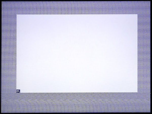
With the collapsed DFILE, there are only the newline characters, no spaces are drawn, so you see only the background.

This is clearer when there is text on the screen, you can see where characters are drawn, but with no additional white space at the end of the lines.

Normally this would not be visible to the user, as the background is white.

Horizontal Sync
When the NewLine character is encountered, the NOP generation logic is disabled and the Z80 reads the NewLine character code as an instruction and executes it. As previously stated, this is the op code for HALT, and so the Z80 halts.
The Z80 remains in the halt state until the end of the line.
The refresh cycles continue, and the refresh address continues to count up. The address range has been chosen so that by the end of the line it will have reached an address where A6 is low. A6 is hard wired to the /INT pin, so this causes an interrupt and wakes up the Z80. The interrupt handler in the ZX80 ROM sets up the refresh address for the next line and then jumps into the DFILE again. (this unfortunately means it's tricky to use hardware interrupts for other things on the ZX80)
Whilst doing this, the Z80 generates an interrupt acknowledge signal, an IO request with /M1 low. The /IORQ line going low sets the Q output of the first flip high and its /Q output low. This is clocked through the second flip flop by the rising edge of M1 (which is the falling edge of the /M1 signal).

That low pulse is then clocked into the third flip flop by the next falling edge of /M1, and this sets the output Q of the third flip flop low, starting the horizontal sync pulse.
This low is fed back and clears the first flip flop, sending it's /Q output high. This high is then clocked through the next two flip flops on the next to falling edges of /M1, ending up with the Q output of the third flop flop going high after around 6uS.
That high ends the horizontal sync pulse, the first flop flip is no longer in clear mode, but the /Q output remains high until the next interrupt acknowledge sets it low again.

When the collapsed DFILE is in use on a ZX80 with less than 4K of RAM you can see it spends the remainder of the lines in halt, waiting for the refresh address counter to trigger the interrupt.

The border lines at the top and bottom of the screen look similar to the above collapse display file version, the address is set so the first character read is always a newline, so the Z80 is halted for the full length of the line.
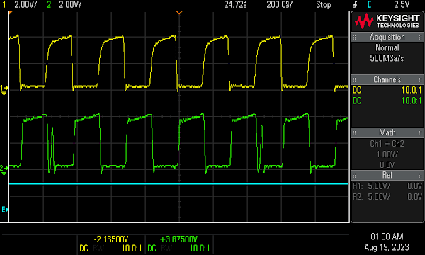
These traces show a full line, with the combined sync in blue, video in green, and the composite video in yellow (at the base of the output transistor).

This process of line drawing continues until all the display lines and border lines have been completed.

The VSync signal discussed above is then generated and merged with the horizontal sync pulses at the last stage of a flip flop chain, where the VSync pulse drives the clear input and forces the output low for the duration of the 384uS pulse.
During this pulse, the keyboard is scanned and the end of the vertical sync pulse takes us back to the top of the screen again.

And so on, 50 or 60 times a second until a key press is detected.
Back Porch
Looking at the line end, you will see an extra ledge on the yellow composite video trace, this is the "back porch" signal required to set the black level, you will see the video signal only goes down to the black level, and not as far as the sync pulse. (to be technically correct, black level should be 0V, the sync pulse -0.2V and the white level 0.7V, but most of the time it is fine to generate a 1V P-P signal with the sync at 0V.)

The front porch on the left is a little slow transition, due to additional capacitance in the circuit below, but it does not seem to cause a problem.
This signal was missing on the original ZX80, and is handled on the Minstrel 2 by an additional logic chip, as discussed in this series of blog posts:
http://blog.tynemouthsoftware.co.uk/2022/09/minstrel-2-pixel-synchronisation-part-1.html

Here yellow now shows the modified video signal as it leaves the second flip flop, with the new low pulse which is the duration of the HSync pulse, plus the extra back porch section. It does not matter that it is also low during the HSync pulse, as that will override the output and take it fully low.

Pixel Synchronisation
The other thing the new circuitry does is corrects a display glitch that is only visible due to modern monitors, and gives a cleaner output.

A simple 10 PRINT program generates a screen full of chequerboard patterns

Here you can see the green pulse from the output of the 165, complete with a glitch every 8 pixels, and the yellow cleaned up version which is delayed by one clock cycle, hence appearing inverted.
Flicker Free?
The flicker every time a key is pressed or code is being run is annoying when typing in programs, and limits games to challenge - response type games, things like Space Invaders being difficult to play if the screen flashes whenever you press a key.
The Software Solution
On the ZX80, programmers worked out that they could bypass the normal screen drawing code and draw the screen themselves, and execute their game code. The only catch is the code had to take exactly the same number of cycles to run, no matter which code path it went down, making it a challenge to code. But, very rewarding, as you can have so called "Flicker Free" games which were a lot more playable as you could now have Space Invaders and Donkey Kong etc.

See Paul Farrow's excellent site for more information on techniques used and some modern games which benefit from the flicker free game mechanic.
http://www.fruitcake.plus.com/Sinclair/ZX80/FlickerFree/ZX80_DisplayMechanism.htm
See also George Beckett's research into this to create his flicker free ZX80 port of Hampsons Plane.
https://github.com/markgbeckett/zx80/tree/main/hampsons_plane
Whilst I am doing links, I should also credit Grant Searle for his work on understanding the ZX80 and ZX81, which has been very useful throughout all of my Z80 related tinkering.
http://searle.x10host.com/zx80/zx80.html
The Hardware Solution
One of the key aims of the ZX80's replacement, the ZX81, was to remove the flicker when keys were pressed etc. They did this by introducing a mode where user code could be run in the blank areas at the top and bottom on the screen.
In the next post, I will look at how the ZX81 does this, and how the Minstrel 3 replicated this functionality.
http://blog.tynemouthsoftware.co.uk/2023/10/how-the-zx81-generates-video.html
Advertisements
Minstrel 2

The Minstrel 2 is a ZX80 compatible kit. It largely follows the original schematic, with the addition of 16K of RAM, and a modern ROM chip and the improved video out with back porch and pixel synchronisation as shown above.

The latest version includes pads to fit a pin header next to the edge connector. That was very useful during the creation of this post to attach all the logic analyser probes.

Minstrel 2 kits are available from Z80kits.com
And also in built, kit and PCB only form from SellMyRetro
- Built and tested with dual keyboard - https://www.sellmyretro.com/offer/details/63942
- Built and tested for ZX81 case - https://www.sellmyretro.com/offer/details/62386
- Full kit with dual keyboard - https://www.sellmyretro.com/offer/details/63946
- Full kit with no keyboard - https://www.sellmyretro.com/offer/details/63729
- Keyboard kit with 4K keywords - https://www.sellmyretro.com/offer/details/63944
- Keyboard kit with 8K keywords - https://www.sellmyretro.com/offer/details/63943
- PCB only - https://www.sellmyretro.com/offer/details/62001
- Keyboard PCB set 4K keywords - https://www.sellmyretro.com/offer/details/61984
- Keyboard PCB set 8K keyboard - https://www.sellmyretro.com/offer/details/62033
- Keyboard PCB no overlay - https://www.sellmyretro.com/offer/details/61986
See also Minstrel 3 (ZX81 compatible) and Mini PET (Commodore PET compatible) kits, more info here
And Minstrel 4D kits (Jupiter Ace compatible)
Patreon
You can support me via Patreon, and get access to advance previews of posts like this and behind the scenes updates. These are often in more detail than I can fit in here, and some of these posts contain bits from several Patreon posts. This also includes access to my Patreon only Discord server for even more regular updates.
https://www.patreon.com/tynemouthsoftware
