
Hopefully, when you build your Minstrel or Mini PET kit, it will work first time. Most of them do based on the feedback I get.

Occasionally, there can be problems, so I present a bit of a guide to the process of troubleshooting if it doesn't work first time.
This can also serve as a guide to follow before you power on for the first time, if you want to take things slowly and carefully.
Test Procedure
First thing to do before putting any of the ICs in is to give the board a thorough visual inspection.

You are looking for missed solder joints, there are over 800 pads on a Mini PET, so it's easily done. You are looking for components that are missing or in the wrong place, solder bridges, any loose bits of solder or any scratches or other damage to the PCB.
Once you are happy, it is time to double check the polarity jumpers and plug in the power.
The LED will not light at this stage, so don't worry about that.

I have indicated all the places you should be able to measure 5V. I normally check on the top left 74LS07. There should be 5V between pin 7 (black) and pin 14 (red). You can check a few of the other places if you like, but that chip is the furthest away, so if it is OK, it should all be OK.
The same procedure can be followed on any of the other kits. Most of the ROM, RAM and logic chips have 0V and 5V on those opposite corners (apart for the 74LS93 on the Minstrel 2 for some reason). However, the 40 pin IO chips and microcontrollers are anyone's guess, check the included schematics..
If you don't see 5V, check around the power input (you did fit the jumpers? and you did set them correctly for your power supply? and you did plug it in to the wall? and you did switch it on). Look for 9V on the left most pin on the 7805.
If you have 5V, you can turn off and start to fit some chips.

With the CRTC microcontroller and the four logic chips next to it, you should get a video display. Set the DIP switches appropriately for your display.
The Ready LED should light a few seconds after powering on.

At this stage, it should have video sync, but just a blank screen (note the important difference between no video output and a black screen with sync).
(do you really need me to take a picture of a black screen? OK, like this ■ but larger)
If you install the character ROM and the video RAM you should see random characters.

That is the same thing you will see on a real PET just before the display appears. This is the contents of the uninitialised static RAM.

At this point you have a working display, showing the contents of the video RAM. Now we need something to write to the video RAM.
The minimal configuration to get some code running is as follows: the 6502 CPU, the ROM, reset buffer, read/write signal control and address decoding.

Set DIP switches 1, 2 and 3 on to enable the PET Tester ROM.

It should cycle between a character set and a page of letters. There is no RAM, so it should all report "B" (for bad).

Next, install the RAM, and you should now see a page of "G".

That's better, all good (well, at least the first 1000 bytes anyway)

In order to run BASIC, add the 6522 and the lower 6521 and the 74LS145. That should be everything to get the PET running and reading the keyboard. Set the ROM selection to 1, 2 and 3 off to boot to BASIC.

You can attach the keyboard and test things out. The datasette should be working, as should the sound and everything apart from the IEEE-488 port.

All being well, the final step is to install the remaining things that are only needed for the IEEE-488 port, and then you can plug in your SD2PET (you did order an SD2PET, didn't you?) and test that.

What if it doesn't work?
If any of these stages fail, you should be able to narrow it down to the bits added since the last stage. Check around the IC sockets and related components.
The standard process I follow in this sort of situation is to go through the following list, checking each in turn, looking for anything which isn't there, or where the signal is not right.
- Power
- Clock
- Reset
- Data lines
- Address lines
- Chip enables
- Read / Write
- Interrupts
In a circuit like this with CMOS logic, all the signals should be nice and sharp 0V or 5V, nothing in between.

The power has already been checked, so first on the list is the clock.

There we are, nice and clean, 1.000MHz. A bit of ringing, but that is due to non-ideal measurements conditions (I am clipped onto the ground on the other side of the board).
Keep going through those signals, checking the operate as expected. E.g. Reset, this should be low for a second or so (at the same time as the LED is off) and then stay high.
Extended Testing
Once you have BASIC running, you can go on to test the rest of the features.
Starting with the datasette ports.

No spikes, just checking.

Although it isn't used much, I did check out the second datasette port. Changing the jumpers so that the rear edge connector becomes device 2.

I start with the tape stopped, so I can see it detects that correctly, and starts when you press play.
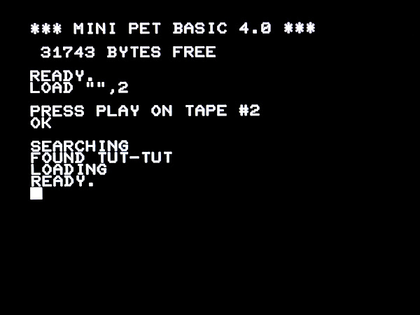
And there is Tut-Tut as well.

To test the userport, I used a dual joystick module.

Testing that with my TFW8b special black and white joystick (which I thought was top secret, but Chinny has done a video on them now, so maybe it isn't).

I suppose if you want the fully loaded Mini PET, I should add the SD2PET power tap and a datasette drive.

As a side note, I wouldn't normally use the PET Diagnostics with a Mini PET. It works, but it shouldn't really, so is not listed as supported. The clock arrangement is different; on the Mini PET it is generated by the CRTC and fed to the CPU, the output clock from the CPU is ignored. The PET Diagnostics uses the output clock to drive the system during testing, so the read and write timing is not going to be right.

It will detect things such as lines stuck low though.

All the ROM and RAM tests pass.

It doesn't have checksums to compare for the self test ROM or Mini PET BASIC 4.0, but then I never planned to use it with the Mini PET boards.
Advertisements

The through hole kit versions of the PET Dual Joystick have now been listed on SellMyRetro:
- Assembled - https://www.sellmyretro.com/offer/details/64260
- Full Kit - https://www.sellmyretro.com/offer/details/64257
- PCB Only - https://www.sellmyretro.com/offer/details/64256
(this replaces an assembled surface mount version that I had designed for TFW8b, which they are not selling anymore)
The full range of Minstrel and Mini PET kits and accessories are available form my SellMyRetro store.

This post was written last month, and was put live for my Patreon supporters. Since then, I have run out of the original Mini PET V1.48 boards as shown here. I am now shipping the slightly updated V1.49 boards. More on those in a future post.

All the links can be found here:
Patreon
You can support me via Patreon, and get access to advance previews of posts like this and behind the scenes updates. These are often in more detail than I can fit in here, and some of these posts contain bits from several Patreon posts. This also includes access to my Patreon only Discord server for even more regular updates.
