
This is one of those cases of requirements creep, or "oh, that's a good idea, let's add that".

It started with a suggestion from my discord that I should make a module for the Minstrel Expansion Bus that clicks when you type on the keyboard, like the ZX Spectrum does and the ZX81 doesn't.
OK, that sounds interesting, I think I can do that.
The basic principle is to detect reads of IO address $FE. That will be reading the onboard 8 bit input port. This includes 5 bits for the keyboard columns, the cassette ear input and the PAL/NTSC switch.
When that is read, the results are placed on the databus, so in theory if I decode the address and then read the databus, I should be able to read what is placed on there by the buffer.
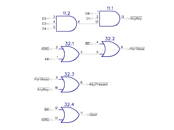
A very simple circuit at first attempt. Minimal decoding (since that is the same employed on the ZX80 / 81 and Minstrel 2 / 3 etc.) to get a "keyboard port is being read" signal. This goes low when the port is being read.

The 5 keyboard columns are pulled up to 5V, and when a key is pressed it is connected via a diode to one of the high address lines. When that row is being scanned, the address line is taken low, and the signal is pulled low via the diode.
I don't care which key is being pressed, so I can just AND them together (using an imaginary 5 input AND gate for illustrative purposes).

That will be high normally, and goes low when any key is pressed. If I were to OR /AnyKey and /PortRead together, I would have a signal which goes low whenever a key is being pressed.
I could just wire that up to a piezo.

Finished, job done. Export gerber files and click order.
Well, no. That pulse will be really short, so will barely register. I need to make the pulse longer.
I did think about using a 74HC123 one shot, or even a 556 dual timer, and maybe I should.
I thought about the options and remembered there is a second signal I could recreate. Following the keyboard scan pulses, there is an IO write, which is used to trigger the next video line to be drawn.
If I use the brief "key pressed" pulse to trigger a flip flop, I can use the matching IO write pulse to clear it. Giving a much longer pulse, approximately 180us to 380us long, depending on which row the key is on. This will repeat every frame, giving a pulse every 20mS, a 50Hz hum which should be OK for a "click".
I used a 74HC74 for that.

I routed out a board, but there is some space left.......
Oh I know, I can add an LED. That is using the Q output of the flip flop, I could use the /Q to drive an LED.

But the 74HC74 is a dual flip flop. Shame to waste the other half ....
Oh I know, can I add an indication of cassette load data? Well, that is bit 7 of the same port, so I already have the signals I need.
To make things easier, I'll redraw the schematic a bit at this point. This is the way I normally work, creating small functional groups. Almost like hardware subroutines. I find it easier to follow like that, rather than have to follow wires around a whole page.
I used the other half of the flip flop, with the "keyboard port is being read" signal clocking the data from D7 into the flip flop. This is sampled on the rising edge, which should be the same as the Z80 does, so should be good. (I did at one point have the other flip flop clocking in the "any key" data, but that would have been too short a pulse)
I used the same clear on IO write to ensure it gets turned off after the load, and added a second LED.

Another pair of functional blocks, the /Ear and /Key signals go low when there is data or a keypress respectively.
I initially mixed the signals to the piezo with 470Ω resistors.

However, I thought "what if someone doesn't want to listen to it loading, but does want the keyboard clicks", or indeed vice versa.
So I added some jumpers to disconnect each signal.

But that would mean the signal was at half amplitude if both were active, so I decided to change from a analogue mixer to a digital one, since there was a spare AND gate that could be used to give a clean digitally mixed signal.

I rearranged the resistors so there were pullups on the AND gate inputs to act when the jumpers are removed, and updated the board layout.

That is done, right?
Well I am not a fan of using 2 pin jumpers, where you take those jumpers off and leave them hanging on a single pin, or put one away in a safe place, never to be seen again.
So I changed it to a 3 way jumper instead. That also removes two resistors, so is probably neater anyway.

I think that is the final board, although I haven't actually tested the design yet, I may as well just order some and then I can try it out and if necessary make changes and respin the board next time.

As I said before, I was working on this in the "functional blocks" way, and this is the schematic I was creating along the way as I was designing it.

That's my preference, that's the way I prefer to work. It can be tricky sometimes to find where a particular signal is generated, but as things get more complex, I would move things into boxes or onto separate pages.
I have been asked several times for a single page Minstrel or Mini PET schematic, and I have tried, but it is a lot of work, and I don't find the results particularly easy to work with.
I have redrawn this fairly simple circuit "all in one". Do you find that easier to follow?

It is a bit like comparing the multi page schematics of the PET with the huge single page of the BBC Micro. I have spent many many hours with both of those schematics, and I have to say I would chose the Commodore way every time.
The same with the ZX80 schematic, redrawn here by Grant Searle

Back in 2016, I redrew that for the Minstrel 1 (as it wasn't called). I was fairly new to the PCB software, so I used busses. I think I started with the three busses used on the original diagram, but ended up merging them into one big one. Not very easy to follow, but it was really just to get the parts wired up to be able to create a PCB.

When I came to do the Minstrel 2, I decided it was best to redo that. It still follows pretty much the same schematic, but I redrew it in functional blocks. That has now grown to an 8 page schematic with things in separate blocks.
That's just easier for me to follow.
An example page: (the bottom right block is the new stuff).

Any thoughts, which type of schematic do you find easier to follow?
Advertisements
The Minstrel Input Monitor Kits are available from my Tindie store:

Various other bits for the Minstrel Expansion Bus are described here:

My store also contains the full range of Minstrel and Mini PET kits and accessories, best to use the contact me link about, tell me what you want and where you are and I will send a PayPal invoice. Sorry I have to keep saying that. I am working on an alternative.

All the links can be found here:
Patreon
You can support me via Patreon, and get access to advance previews of posts like this and behind the scenes updates. These are often in more detail than I can fit in here, and some of these posts contain bits from several Patreon posts. This also includes access to my Patreon only Discord server for even more regular updates.
