Friday, 17 February 2017

VIC20 Repair

The Penultimate Cartridge was launched last year, and between the initial units I sold and all the production units that have been sold by The Future Was 8 Bit, there are quite a lot of them out there.
I'm pleased to say that with all those units that have been sold there have been no returns. We almost had one, here's the story.
A user had just bought a Penultimate Cartridge and reported it was behaving oddly. The menu was appearing, and games could be loaded, the problem came with the RAM, anything over 8K was failing. This is odd, as the design has been proved to be reliable, and all the units are tested before and after being installed in their cases, so we wouldn't expect any failures. The user had done a bit of testing, and was happy to do a few more tests to try to identify the problems.
Time for some quick revision on the VIC20 memory map. The 6502 in the VIC20 has a 64K address space. This is split into 8 blocks of 8K, allocated as follows:

Block
Address Range
Use
0
0000 - 1FFF
Internal 5K RAM + CART RAM1/RAM2/RAM3
1
2000 - 3FFF
Cart BLK1
2
4000 - 5FFF
Cart BLK2
3
6000 - 7FFF
Cart BLK3
4
8000 - 9FFF
Video / IO space
5
A000 - BFFF
Cart BLK5
6
C000 - DFFF
BASIC ROM
7
E000 - FFFF
KERNAL ROM

A cartridge can add ROM or RAM at blocks 1,2,3 and 5, and also 3K of RAM into block 0, as three 1K blocks at RAM1, RAM2 and RAM3 (hence the maximum = 4x8K + 3x1 = 35K). 8K was working, so was 11K, so block 0 and block 1 were OK, but as soon as RAM was added to block 2, it would fail. In order to narrow things down, I asked the user to try a few games. The VIC20 will automatically start a ROM with an appropriate signature when placed in block 5. Most cartridges use an 8K ROM in block 5, and many also have an additional 8K ROM in another block. There isn't a standard here, some use block 1 some block 3. I suggested testing the following games:

Game
Blocks Used
Avenger
5
Centipede
5 + 1
Defender
5 + 3
Adventure Land
2 + 3

Avenger, Centipede and Defender all worked fine, so blocks 1, 3 and 5 were OK. Adventure Land required block 2, and that wasn't working. So again this was pointing to block 2. This exonerates the RAM chip, but points the finger at one of the following:

  1. Something in the cartridge responding incorrectly when block 2 was selected
  2. A bad contact on the edge connector carrying the block 2 signal
  3. Something inside the VIC20 causing an issue with block 2 access

The user had already cleaned the edge connectors, and they looked fine, which seems to rule out option 2, so the cartridge was return to TFW8B for testing. When received, it tested fine, so that rules out 1. The only candidate remaining was a fault in the VIC20. The user wasn't too far from me, so dropped his VIC20 off for further testing.
All looks well inside, nice clean VIC20 CR. This later version of the VIC20 was fairly reliable, it is usually the kernal ROM or VIC chip which goes, coincidentally, the only factory socketed chips on the board.
I tried it out using my prototype Penultimate Cartridge, the LEDs on here show the mode and ROM image selected, and these were showing the right thing, so the cartridge was operating as it should, but was still failing memory tests.
Inside the VIC20, there is a 74LS138 chip which generates eight signals, one for each block of memory, each of which is normally high and is pulled low when that block is selected. Looking along the pins on the oscilloscope, all the pins were high as expected, with blocks 0, 4, 6 and 7 being used in normal operations, and blocks 5 and 3 also pulsing low when the Penultimate Cartridge menu was being used. Block 1 was high as normal. Block 2 was floating low all of the time. Bingo. There's ya problem.
I swapped that chip out and retested and everything now ran fine. Block 1,2 and 3 could be filled with RAM and that all passed memory tests. When that line was floating low, as soon as any ROM or RAM was connected to that pin, it would be enabled all the time, not just when the block was accessed, so would have caused errors throughout the address range, explaining the strange behaviour.
I've run through the Penultimate Cartridge tester a few times, and it has passed. I retested with a different Penultimate Cartridge and several original Cartridges, and finally had the users original Penultimate Cartridge sent up here from TFW8B.
That again passed all the tests. I also tried some large games loaded from SD2IEC, like Pentagorat which needs 32K of RAM and Doom which needs 35K.
All done and ready to return to the user with his original Penultimate Cartridge. That VIC20 might have been like that since new, never a problem until something larger than 8K was added to the cartridge port. I've checked and unfortunately, the warranty from Commodore has run out.

Update: A similar (but less common issue) - http://blog.tynemouthsoftware.co.uk/2022/11/vic-20-repair-the-vic-that-did-not-like-cheese-and-onion.html

2022 Update: The production version of the Penultimate Cartridge is now available from  The Future Was 8 bit

Monday, 13 February 2017

PET MicroSD

This is an old post, preserved for reference.
The products and services mentioned within are no longer available.

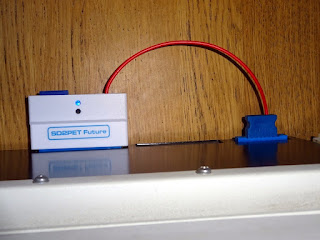
This post has been left for historic information. The PET microSD is no longer in production. The replacement SD2PET is available now, more information on the pre-order page.

The PET microSD is an SD card disk drive for the Commodore PET. I have been making these for a while, but they have been out of stock recently as I have been preoccupied bringing some new products to market (namely the VIC20 Penultimate Cartridge, the Minstrel ZX80 Clone and the DivMMC Future).
I've decided the best thing to do is to setup a preorder for the PET microSD, to gauge demand for the different types and get some more boards ordered and some more units built up. There are three types of PET microSD boards. I was hoping to simplify this list, but for the moment, I'll leave them as they are.

PET microSD Horizontal

This is the original build. It sticks out of the back of a PET and is powered from the datasette port. This is suitable for any PET with IEEE-488 and datasette edge connectors (so not the 8032-SK). Note the power connector no longer sticks out as much as the version shown here.

PET microSD Vertical

This also fits on the back of the PET, but is low profile, so does not stick out as much as the Horizontal. Again suitable for most PETs except the 8032-SK.
It is powered by a 9V DC tap from inside the PET, normally by plugging into the expansion power connector (J11).
If J11 is not present, or in use for something else, it can be powered by a clip onto a diode near the power connector. The 2001 does not have J11, and the 8096, 8096-SK and things like the Super PET use J11 for expansion boards, so these would need the power clip. The rest can use J11 for power.

PET microSD Internal

This version fits almost totally inside the PET. These is a small loopback board which plugs into the back and passes the signal back inside. This is also powered via the 9V tap as above.
This is suitable most PETs, and these is a version with an edge connector suitable for the 8032-SK, this will allow the rear IEEE-488 port of the 8032-SK to still be used.

Pre-Order

This is a pre-order for the next batch of PET microSD boards. All are supplied with a microSD card preloaded with some example software to get you started.
UPDATE:  the final batch are now all accounted for, and I have no plans at the moment to build any more, so please consider these discontinued. I am working on a replacement product, more information to follow.

Notes
  • When I say PET, I mean PET and CBM and CBM-II
  • When I say 8032-SK, I mean 8032-SK and 8096-SK machines with rounded cases and separate keyboards
  • When I say 2001, I mean 2001 series PETs with chicklet keyboards and built in datasettes
  • When I say 2001N, I mean 2001-8N/-16N/-32N and other 2001N machines, which were also called the 3000 series and 4000 series. All with 9" screens, and full size keyboards.
  • PETs with BASIC version 1 will need to be upgraded to BASIC 2 or BASIC 4 (why not use a PET ROM/RAM board)
  • Click here for a full list of which PETs support which version of PET microSD
2022 Update: I have since designed a much nicer SD drive for a PET. The SD2PET is available from  The Future Was 8 bit

Sunday, 29 January 2017

Minstrel ZX80 Clone Issue 2

This is an old post, preserved for reference.
The products and services mentioned within are no longer available.

This is the Tynemouth Software Minstrel Issue 2. It is a ZX80 clone with a few concessions to 2017. This fixes a few issue with the issue 1 boards (the missing link and the keyboard connector pinout)
Following testing on the issue 1 boards, I have added an extra chip to improve the composite video output. These is now also a reset switch on board, and the list of the extra ZX80 commands that is on the ZX80 case is duplicated on the silkscreen.
The board now has an edge connector and jumpers to select up to 8 ROM images if a 27C512 EPROM is used. The edge connector is the same as the ZX80, but adds ROMCS like the ZX81, driven via a resistor so it can be overridden by an external device.
The power input now has provision for a 7805 regulator mounted ZX81 style with heatsink, or a switch mode 7805 replacement. Power in is via a 2.1mm DC jack, with jumper selectable centre negative (ZX Spectrum, Commodore 16) or centre positive (everybody else). You could use a Spectrum power supply, or a modern replacement. Current draw is less than 200mA, more if you plan to draw any power from the expansion slot.

Build #1 - ZX80 Clone 4K ROM, 16K RAM

The ZX80 was originally supplied with a 4K BASIC ROM, and a keyboard with blue buttons. This is the classic ZX80. You can build the Minstrel to be a clone of this.
Here I have used a ZX80-KDLX ZX80 style keyboard attached to connectors mounted on the bottom of the board. They do a ZX81 version as well, if you wanted to do one of those.
These are both mounted on a sheet of perspex, the keyboard with double sided tape, the Minstrel board with nylon M3 pillars.
I've soldered in all the TTL chips on this one, and hard wired all the jumpers.
This runs the original 4K BASIC, so the keyboard matches that. W shift Y shift Y for LOAD ""

Build #2 - ZX80 Clone 8K ROM, 16K RAM

When the ZX81 was released, Sinclair also provided an upgrade for the ZX80. A new 8K BASIC ROM, and a new keyboard overlay with grey keys, that looked just like the ZX81. This allowed it to run much ZX81 software, but it didn't have slow mode, so many of the more graphical programs wouldn't work. You don't see many of those around, as I expect most people prefer to see ZX80's with the blue keys. If you want grey keys, get a ZX81.
So that's what I did. This ZX81, however, doesn't work, so will be the basis for the second build, a ZX80 8K BASIC clone.
Inside the ZX81 case was an issue 3 ZX81 board. I'll probably repair it later, but for now I am going to swap it for a Minstrel board with the ZX80 8K BASIC ROM.
The Minstrel board was designed to be a drop in replacement for ZX81 case. If you are building your own, you can borrow things like the keyboard connectors, Z80, 7805 and heatsink from the original board.
The membrane on the ZX81 case was cracked. You can sometimes repair these, but I gave up on this one and fitted a new ZX81 membrane from RWAP. It's easier to work with the new ones as they are very flexible, the originals get very brittle in their old age.
The board is attached to the case lid with 2 screws. There are 5 possible positions, 3 of which are used to screw on the base, and 2 hold the board in place. The Minstrel board has white silkscreen around the two screws that need to be fitted at this stage.
The red paint on the ZX81 logo on the case was partially missing, so I gave it a helping hand, and now the ZX81 logo is black. I was tempted to paint that white, or even spray the whole case white. I did get a can of spray paint, but it said use outdoors, and the temperature must be over 10 degrees, so will have to wait until July. I quite like it with the all black logo. The Darth Vader ZX80 (or the Master's ZX80 depending on your allegiance).
The connectors all line up with the original, the top one is now composite video, and the bottom uses a 2.1mm DC jack for power, rather than the original 3.5mm jack.
Since this is running the 8K BASIC ROM, the keys all work as marked, it is now the more familiar J shift P shift P to get LOAD "" on the screen.
If you look carefully, the font is different, a slashed zero on the later version.

Build #3 - ZX80 Clone 4K or 8K ROM, 16K RAM

The final of the three of these I have built has both ROMs installed, jumper selectable, and uses an RC2014 keyboard.
The pinout of the keyboard is slightly different, so I made up a lead with the rows rearranged. I've also replaced the diodes on the RC2014 keyboard with wire links as the diodes on the ZX80 are reverse biased.
This one has all the jumpers fitted, so I can test out NTSC and inverse mode and various different ROM images.
I have built all of these with 74LS series chips, the same as the original used.
I have tried with 74HCT, and it does work, and draws about a third of the power. The choice is yours. I haven't tried 74HC, less likely to work, as is a mixture, go for one type or another.
When I started the Minstrel ZX80 Clone, I had a few aims in mind.
  1. Create a ZX80 clone using the 4K ROM and original keyboard layout.
  2. Create a ZX80 clone using the 8K ROM which will fit into a ZX81 case
  3. Create a ZX81 clone with NMI mode which will fit into a ZX81 case
These issue two boards address the first two of those. The third one will follow in due course, I am deviating from the ZX80 design and adding in various upgrades, such as the NMI controlled slow mode which will make it fully ZX81 compatible.

Assembling a Minstrel ZX80 clone

Assembly should be fairly straightforward, they are all through hole parts. I've changed the silk screen to show values rather than part numbers, so it is just a case of putting 1K resistors in all the spaces marked '1K'.
Start with the resistors.
Then capacitors and diodes.
Then IC sockets, if you are using them.
Finally the connectors.
All of the ones I have built here have worked first time, and that should be the case as long as you make sure all the parts go in the right place and the soldering is reasonably neat, and as long as you are using good parts. No guarantees if you are using any IC's you got 'from a bloke in a pub'.

The Minstrel boards, overlays, kits and built units are available from my Tindie store.


2022 Update: PCBs, kits and occasional built kits are available from my SellMyRetro store.

https://www.sellmyretro.com/store/tynemouth-software