Saturday, 9 February 2019

USB Arcade Controllers

This is an old post, preserved for reference.
The products and services mentioned within are no longer available.

Last  year I built a Picade kit from Pimoroni, it's been great and has had a lot of use by me and my nephews.
The only thing I had an issue with was the buttons and they way they were mapped, the joystick is the cursor keys, which is fine. The keys on the side and enter and escape, which is also fine, but the buttons on the top and the two on the front are mapped as shift, control, alt, z, x, o, i and space, which didn't really make sense and confused a few emulators which used those keys for other things.
I missed the clicky sound of microswitched buttons, so decided to fit some to replace the original low profile switches. They are the same diameter as normal arcade switches, so it was a simple job to swap them over.
I ordered some standard microswitched arcade switches (from arcadeworlduk) and wired those up.
I had ordered a selection of colours, so I colour coded the wiring, with two wires for each switch rather than a common ground.
I also took the opportunity to solder in and heatshrink the wires on the power button as the crimp tags felt a little loose.
I arranged the new buttons to try to match the colours of other four and six button arrangements - the blue and purple are more distinct that they have come out in the photos.
It was all a bit of a tight fit, getting in those six buttons, and four black buttons around the base of the case, but it all fell into place in the end.
Since the button usage was now more consistent, I used the stickers supplied with the Picade kit to label up some of the buttons. Did I get it right, are there better arrangements?
With all of those wired up, it was time to plug them in. I think by adjusting the setup script on the Pi I should have been able to map these to different keys still using the Picade X Hat controller, but decided to go a different way. I have found in the past the best option with Retropie was to use a game controller with lots of buttons and dedicated start and select buttons.
This is the replacement board I designed, it is a USB game controller with inputs for a 4 way joystick and up to 8 buttons.
Each of the inputs has it's own ground connection along the bottom of the board, all are switched to ground, no multiplexing or keyboard matrix is used here.
The original joystick was microswitched, so I left that as is. It was on a connector with 5 pins on, so I fitted a matching 5 pin socket. The buttons are connected to eight 2 pin headers, each with it's own ground. It could have been wired with a single ground wire, but it's neater and easier to swap things around using a 2 pin cable for each button.
That mounted nicely on the side of the case. The power switch and power LED are left wired to the Picade controller as before. With that connected and RetroPie reconfigured, it seemed to work a lot better with two buttons on the controller dedicated to start and select (the two on the front) and the 6 action buttons as X Y A B, left shoulder and right shoulder..
The two buttons on the sides of the case were setup originally as Enter and Escape. This seemed sensible, so I left those plugged into the Picade X HAT controller.
I had thought I might need to add more buttons, so I also designed an extension board, which has 64 inputs to act as 64 keys on a USB keyboard. As before, these are all individual inputs switch to a common ground.
That would allow individual arcade buttons to press any key you want, such as keys for coin up, player selection, F1 or F12 for menus, any of the letter or number keys etc. You could wire up a joystick to WASD, or to 5678 for Spectrum fans or anything else you can think of.
These are plug in and go, just wire a switch between any of the ground pins and "A" and when you press the switch it will be like you pressed "A" on a normal USB keyboard. I can see this would also be useful for creating those massive controllers people have for flight simulators etc. or adding buttons for menus, changing games, coin up etc.
These boards are available from my Tindie Store, with or without the keyboard extension.
In the usual DIY kit form with the built, programmed and tested controller board, mounting pillars and a USB lead.

Sunday, 3 February 2019

8K or 16K ROM Cartridge PCBs for Commodore VIC20

This is an old post, preserved for reference.
The products and services mentioned within are no longer available.

Yellow is the new green.
At least as far as VIC20 Cartridge PCBs go. These are the new 8K or 16K ROM cartridges from The Future Was 8 bit.
There are instructions on the back, but I'll go through the options in a bit more detail. First a quick refresher on the VIC20 memory map. The 6502 can address 64K (without paging), and on the VIC20, this is split into eight blocks. four (and a half) of which are assigned to the cartridge port.

Block
Address Range
Use
0
0000 - 1FFF
Internal 5K RAM + Cartridge RAM1/RAM2/RAM3
1
2000 - 3FFF
Cartridge BLK1
2
4000 - 5FFF
Cartridge BLK2
3
6000 - 7FFF
Cartridge BLK3
4
8000 - 9FFF
Video / IO space
5
A000 - BFFF
Cartridge BLK5 (autostart)
6
C000 - DFFF
BASIC ROM
7
E000 - FFFF
KERNAL ROM

Block 0 contains the internal RAM, and can be expanded with an additional 3K from the cartridge port (although not with this cartridge). Block 4 is video RAM and I/O space, and blocks 6 and 7 contain the system ROMs. That leaves blocks 1,2,3 and 5 for ROM cartridges. Block 5 is special in that it is checked on system startup to see if it contains a bootable ROM, if it does, that will be started instead of the normal BASIC. These cartridge PCBs can be used to provide a single block (8K mode), or two blocks (16K mode). I did look at adding 4 block (32K mode), but as far as I know, Cheese and Onion is the only 32K cartridge out there, so you should just buy one of those instead.
The locations of the cartridge ROM in memory is selected by means of two four-way jumper blocks. A second set of jumpers also allow multiple images to be fitted into larger EPROMs, and selected via jumpers.
The selections are different depending on the size of the ROM image used.

8K Mode

When using an 8K (or smaller) ROM image, the 8K/16K jumper should be set to 8K. The right hand block jumpers are used to select the block the ROM image will be located at. In almost all cases, this will be block 5, but the options are there for the other 3. In 8K mode, the 74LS00 chip is not used, so does not need to be fitted. Cross jumpers like that need a link making between the centre pin and the selected block. The offcuts from the legs of the capacitors are ideal for this.
In 8K mode, ROM chips from 27C64 to 27C512 can be used to provide between one and eight 8K ROM images that can be selected via jumper, or hard wired. Settings for some common EPROM types are shown below.

A15
A14
A13
27C64
28C64
27C128
27C256
28C256
27C512
0V
0V
0V
-
-
-
-
-
ROM 1
0V
0V
5V
-
-
-
-
-
ROM 2
0V
5V
0V
-
ROM 1
-
-
ROM 1
ROM 3
0V
5V
5V
-
ROM 1
-
-
ROM 2
ROM 4
5V
0V
0V
-
-
-
ROM 1
-
ROM 5
5V
0V
5V
-
-
-
ROM 2
-
ROM 6
5V
5V
0V
ROM 1
ROM 1
ROM 1
ROM 3
ROM 3
ROM 7
5V
5V
5V
ROM 1
ROM 1
ROM 2
ROM 4
ROM 4
ROM 8

In most cases, the easiest option is to set all three to 5V and place the image in the top 8K of whichever ROM chip is being used.

16K mode

In 16K mode, the 74LS00 needs to be fitted (as does it's associated decoupling capacitor). The 8K/16K link is set to 16K mode, and two blocks need to be selected. The left hand block of jumpers selects the block for the lower 8K of the 16K ROM image. The right hand block selects the upper block. The upper block is normally 5, but the lower varies between software houses. This shows blocks 1 and 5 selected (this time using jumpers rather than wire links) and the 74LS00 fitted.
27C64 and 28C64B EPROMs are not supported in 16K mode, so one to four 16K images can be fitted in a 27C128 - 27C512 EPROM. The A13 link needs to be set to 16K now, and the other two are used to select the 16K ROM image within a larger EPROM.

A15
A14
A13
27C128
27C256
28C256
27C512
0V
0V
16K
-
-
-
ROM 1
0V
5V
16K
-
-
ROM 1
ROM 2
5V
0V
16K
-
ROM 1
-
ROM 3
5V
5V
16K
ROM 1
ROM 2
ROM 2
ROM 4

Here I've fitted jumpers, but wire links can be used as before.

Installation

The cartridge PCBs can be fitted directly into a VIC20, the notches on the top edge provide a sort of handle to help remove the cartridge. It goes without saying, but I'll say it anyway for legal reasons, don't install or remove this with the power on.
They can also be fitted into original cartridge cases (to replace faulty cartridge boards for example), or into new The Future Was 8 bit cartridge cases.
I also like to fit things like this to the lower half of the case only, so the jumpers can be changed without opening the lid.

2022 Update: More recent versions of the VIC 20 cartridge PCBS are available from  The Future Was 8 bit Yellow didn't last long, they are blue now.

Sunday, 27 January 2019

Commodore PET 8032 Repair - Screen repeating in blocks

This is an old post, preserved for reference.
The products and services mentioned within are no longer available.

Here we have another Commodore 8032 in for repair, this one looks in reasonable condition this time.
Although I was a little worried when I opened the box, bare boards in polystyrene is probably not a good idea for a static point of view. However it did at least provide good mechanical protection during shipping.
This one is slightly unusual in that the regulators and transistors are all bolted down, apparently from the factory. See my previous post about riveting on replacement regulators.
This is the first time I've seen one that appears to have been bolted on from new, including what I'm sure are the original untouched TIP29 datasette power transistors. I see no reason why anyone would drill the rivets out and replace them with bolts if they weren't faulty. Later PET boards (and all the VIC20 and C64 machines) had the regulators 'flapping about in the breeze', presumably to add a little air cooling rather than heating up the PCB.
The rest of the board looks fine. Like the previous post, this one is from Germany, so has an alternate editor ROM and character ROM to support some inflected letters.
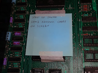
The fault report (helpfully taped to the board) on this one is it beeps (a good start, the CPU, address decoding, KERNAL and editor ROMs and at least some of the RAM and IO chips are working), but it is displaying 'some random characters'.
Oh yes, so it is. Time for PET Diagnostics and see what's going on.
The results are interesting, time for some analysis.
So again, many things are working to get this far. When you see a garbled display like that, it's normal the multiplexor chips that have failed. The 74LS157 switch very quickly between the processor address bus and the video address bus (generated by the 6545 CRTC). This is the later 'universal dynamic PET' board, which can be 40 or 80 column by changing that row of jumpers (old blog post on converting an 8032 to a 4032).
What normally happens is they some of the bits get stuck, and you work out which ones by counting the size of the blocks of repetition or blanks. Here you can see we get 16 characters then a repeat, then 16 OK, the repeat etc. That would point to bit 4. being stuck, and I think there is another error higher up. The video RAM is testing OK though (I think I can read that amongst the rest), and there are various RAM faults as well.
I replaced all three mux chips. When one goes, there's a fair chance more will go. They also have a tendency to fail as they work quite hard.
Unfortunately, that didn't fix it. It cleared up part of the problem, but not all of it. I checked over the work, no shorts, everything testing fine, and the chips were new from the tube. I couldn't see anything wrong there, so I looked further up the food chain. The 157s switches the addresses generated by the 6545 CRTC. The 40 pin chips on this board are socketed, so it was a simple matter of replacing the the 6545 to see if it was that.
Well what do you know, faulty 6545, and probably at least one faulty 157. I need to build a proper tester for these. They usually pass on the chip tester built into EPROM programmers as they test at quite low speeds, and these things tend to do OK at low speed, but in their old age can't do things as fast as they used to be able to do (happens to us all).
I don't like running boards too long in this sort of state, if there are faulty chips writing to the databus when they shouldn't, that can burn out other parts on the same bus, the strongest driver transistors win. I noticed the number of RAM faults wasn't constant, but was worse than the previous photo. I did have time to finish probing around the board, and I found the culprit.
This is the 7905 regulator which generates a -5V reference voltage for the 4116 RAM chips. They always seem to be at jaunty angles and are not bolted or riveted down as the tab is connected to the input voltage, rather than to 0V on the 78xx versions. If you do bolt one down and connect the tab to the voltage rail bad things will happen. It looks like the right hand leg has some extra solder on, as if it had been repaired in the past.
The central leg was sort of touching the pad, but wasn't actually connected. When I had first powered on the board, one of the first things I do is check the supply rails, and -5V was present then, but it's not now. Rather than replace this with a similar part, similarly lacking support, it could snap off again, or vibrate around in shipping. I prefer to replace them with an alternative version of the 7905.
This has a plastic cover all around the tab, so it can be mounted flat on the board without shorting out. There is no problem here with heat, as the -5V is only a reference, and it looks like the board has pads for a small TO18 packaged version. I don't think they make those any more.
Everything is now passing. The editor ROM is consistent CRC, but not a version I recognise. The normal DIN versions are 4K ROMs, but this is on a 2716 EPROM, so it's only 2K. It appears to have a different keyboard mapping to the previous German DIN editor ROM. I'll add it to the list of known CRCs.
It took a while to guess which keys to press again, but I got it to load from tape and seemed to be running well. I couldn't get it to load from IEEE-488, but a closer inspection around the IEEE-488 connector explained that.
These were not fitted from the factory on later models, It looks like someone has fitted a connector to the normally empty pads, but has unfortunately damaged some of the through hole plating in the process.
I did what I could to patch up the broken continuity and got the edge connector active again, and looking extra shinny with a touch of contact cleaner and fibreglass pen.