This is an old post, preserved for reference.
The products and services mentioned within are no longer available.
Quite often, when I get machines in for repair, they come with the statement along the lines that
'it was working fine, then one day it just stopped working'. Usually with no explanation (see an
old blog post for some suggestions). However this time, the explanation was given.
The owner had been using this with the original monitor, but had wanted to move over to a less bulky LCD screen. The Amstrad CPC machines are powered by the monitor, so to do that, you need a separate power supply. He had bought a kit that came with all the bits. As you can see, there is a lot going on here. If you know about the way these work, you may have already worked out what happened.
The CPC 6128's longer, more colourful, little brother, the CPC 464 has two sockets on the back, both connected to cables coming from the Amstrad monitor. 5V DC in and RGB out.
The CPC 6128 in addition needs 12V DC in for the floppy drive, so they rightly decided not to fit an additional socket, and instead added a cable coming out of the CPC 6128 that would plug into the monitor for the 12V.
The kit the owner bought came with two power supplies, one 5V and one 12V. An RGB SCART lead is provided, which taps the 5V power to provide the switching signal to the TV, and a cable which wraps around to the side to pick up the audio out.
As if that is not complicated enough, there are two powers supplies, both with 2.1mm DC jacks. The 5V one plugs into the SCART lead pass through, and then into the CPC 6128. The 12V side is dealt with using a short socket to socket cable which reverses the polarity and the gender, and allows the 12V PSU to be plugged into the lead from the CPC 6128. Can you guess what happened?
Yes, he accidentally mixed them up and sent 12V into the 5V rail. Ooops. When this happens, it can cause all sort of problems. Any of the chips on the 5V rail could have fried. This could be tricky, as in this generation of CPC 6128, almost all of them are soldered directly to the board.
I started with the easy ones. The Z80 and the gate array were socketed, so I swapped those out for known working ones, no change. I did test those two chips out in another 6128, and they were working, so that's a good start, not everything has been fried.
The screen is there, with a random pattern. This could point to a RAM failure. There are sixteen 4164 RAM chips on the board, all soldered in of course. One or more of those has failed. But which ones?
The Z80 in the 6128 has a 64K address range, so cannot directly address the 128K of RAM. The right hand 8 chips form the lower 64K, and these work in the same way as the CPC 464 (which only has 8 chips and 64K of RAM). These are split into four banks of 16K (banks 0-3). The screen uses bank 3, and the stack etc. is built downwards from the top of the bank 2. Since it is not booting, there is at least one fault in the lower 64K of RAM, meaning it is likely that at least of one those eight chips has failed.

The CPC 6128 has an extra 8 chips, another 64K of RAM, forming banks 4-7. There are various modes that are used to access this RAM, controlled by a paging register. The easiest way to use these allows you to access any of banks 4-7 in place of bank 1. To do this, there is a small logic array, a 16L8 PAL. This controls the two highest address lines (which select the bank) and CAS (chip select) lines that go to the RAM chips, so it will enable the appropriate bank of RAM by switching the CAS signal, and if necessary, adjusting the upper two address bits (i.e if you have bank 7 in place of bank 1 the RAM chips need to see a different address to the one that was requested to be read).

Rather handily, the logic array is socketed, so a quick test you can do is bypass all that and setup the upper 64K as the main RAM, so the system is using banks 4-7 in place of banks 0-3. This is only for testing, as it disables the original lower 64K. But this will show if the upper 64K of RAM is OK. The connections are A14 in to A14 out, A15 in to A15 out, CAS to CAS1 and 5V to CAS0 (to disable it). So the address lines are unmodified, and chip select always selects the upper 8 chips, with the lower 8 always disabled.
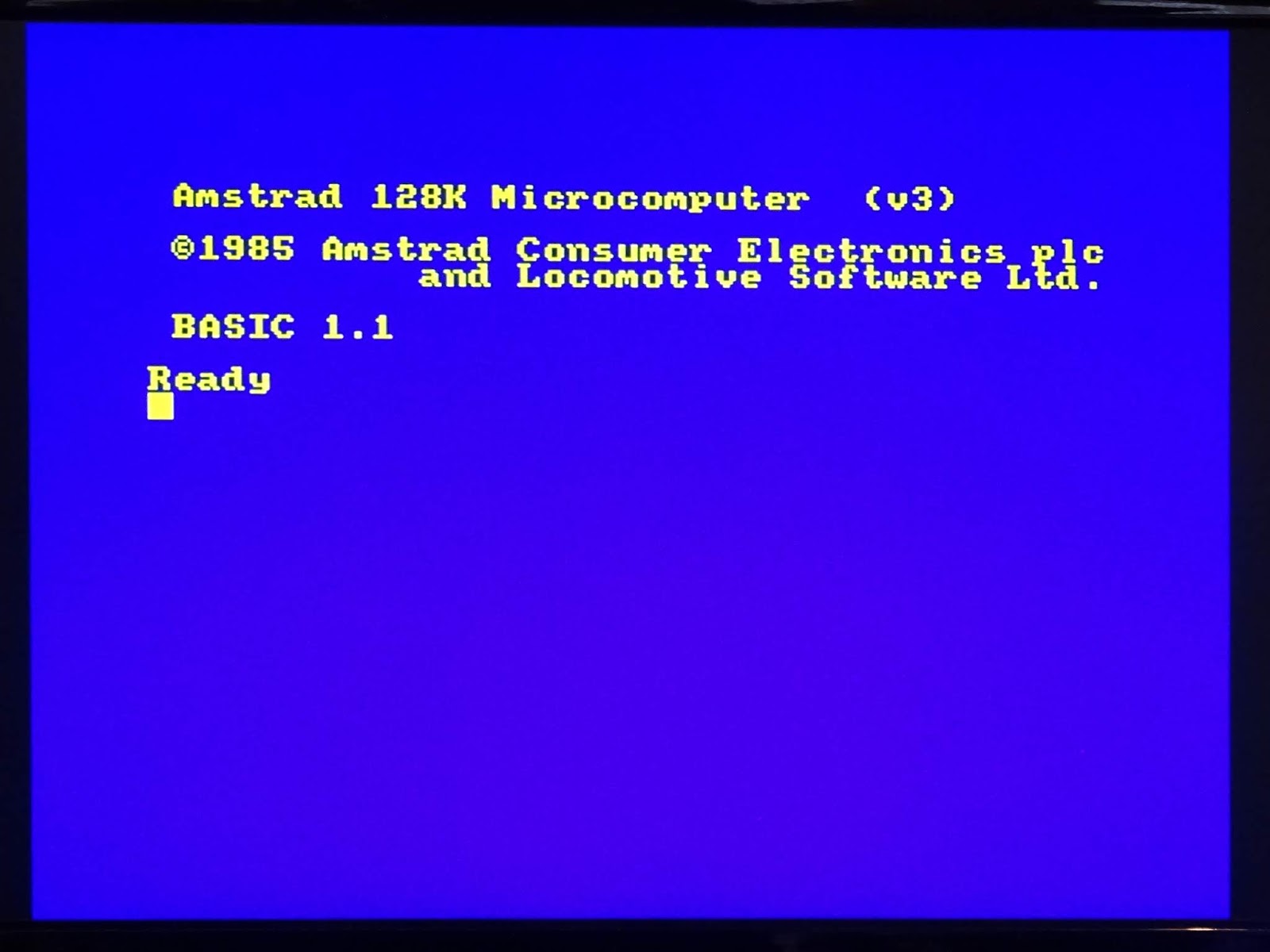
Success, we have a boot screen, and what is now effectively an Amstrad CPC 664. This board is actually designed so it can be 64K only. This would be done by not fitting the upper 8 chips and the PAL chip.
There are two jumpers above the PAL (LK5 and LK6) that can be fitted to link A14 and A15 ins to outs, and another (LK8) which links CAS to CAS0.
So it looks like the upper set of 8 RAM chips (the ones on the left) is OK, so that has narrowed the fault down to the eight chips in the lower half (the ones on the right). But which ones?
It would be possible to do some simple tests from BASIC, if that RAM could be accessed, but it is currently hard wired disabled. However, the PAL chip is compatible with a modern 16V8 GAL, so if I program a new GAL chip, I could control the bank switching. To test this, I wrote a simple set of equations which mirrored with wiring above:
A14OUT = A14;
A15OUT = A15;
CAS0 = 'b'1;
CAS1 = CAS;
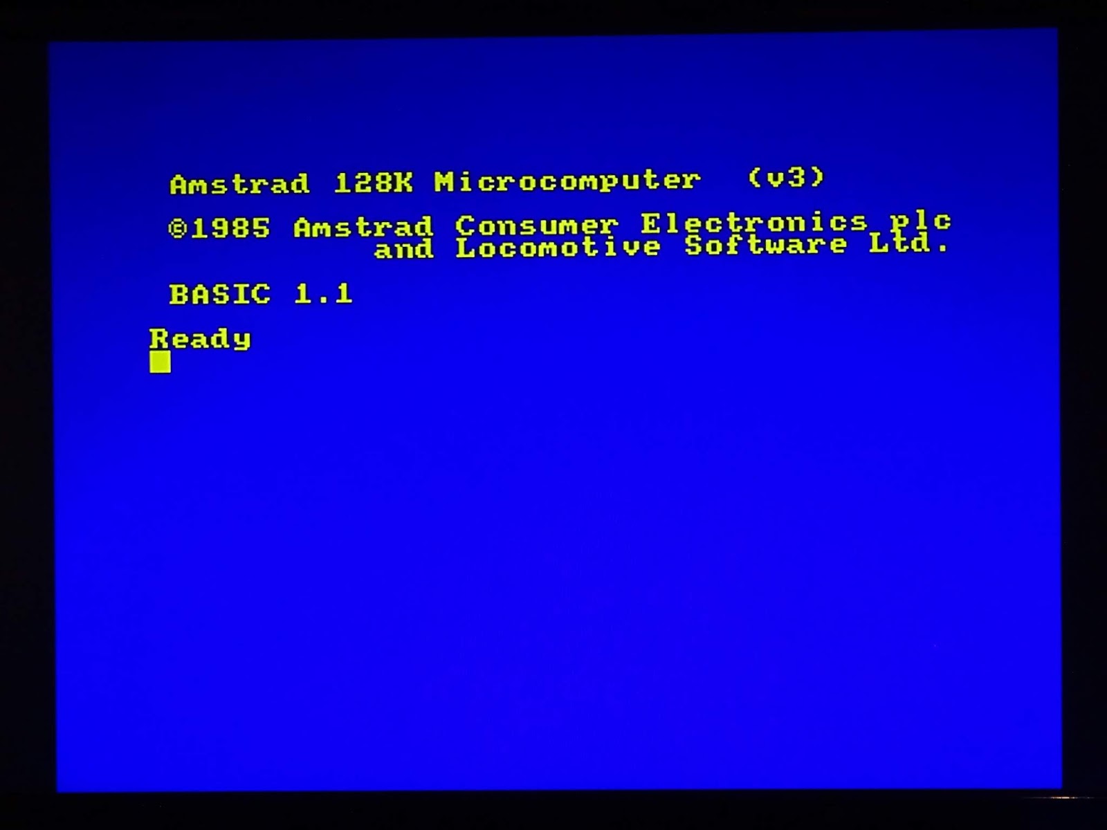
With that burned to a GAL, it again booted. That's handy, that'll save me wiring that up with jumper wires again. Now that I can control bank switching, I think the best option is to set it up with banks 4,1,6,7. That uses the upper 64K for the areas required to boot, but opens a window of 16K in the middle up to the lower 64K (which we know is faulty). With BASIC booted, I would be able to peek and poke at the faulty RAM from BASIC.
A14OUT = A14;
A15OUT = A15;
CAS0 = CAS & !A15 & A14;
CAS1 = CAS & (A15 # !A14);
Maybe not the best way to do it, but CAS0 (the lower 8 chips) is enabled when A15 is low and A14 is high (bank 1). When A15 is high or A14 is low (the other three banks), the upper 8 chips are enabled.
That booted, and I was able to try poking addresses in that range and peeking back at the values. The idea being, if there is a RAM fault, with values will be wrong. I chose the range of 20000 to 30000 arbitrarily as it is comfortably within bank 1 (16384-32767).
The first test program went through poking 0 and checking if the value read back was 0. That would show up any bits that were stuck high. It was clear the numbers were all out by either 16 or 64. (80 is both 16 and 64). Excellent, that is exactly what I wanted to see.
I repeated the test, this time poking 255 to show up any bits that were stuck low, and again it was 16 (255 - 239 = 16). So there are (at least) two failed chips. I removed and replaced the chips which were D4 and D6 in the lower bank and retested.
Excellent, no faults found by my simple test program. Here I added 0x55 and 0xAA to the test patterns to test alternating 1s and 0s. This is a far from complete RAM test, notably there are no test for any addressing problems, but the simple data bus tests all passed.
Next I removed my test GAL and went back to the original PAL, so bringing the lower 64K back into use, with the new use chips, and it booted.
I found a RAM test program presumably for a CPC464, that tested the first 64K, and that passed. (I also retested with the bank 4,5,6,7 GAL to check the upper bank)
In order to prevent this happening again, I've put some heatshrink over the inline connections on the 12V power supply, so it is fixed to the line socket, so the owner shouldn't be able to mix them up again.
It's still quite a convoluted setup, but it's all working nicely.
Disks are reading correctly.
And the programs on them running.
As are cassettes.
And you know what I am going to try loading?
Yes, and that loaded fine.
I played a few levels, and didn't have any problems, so that looks like it's sorted. Ready to go back to it's owner.
I've had a few more Amstrad machines arrive recently to add to my collection, including this one where the packaging is probably worth more than the (faulty) computer inside.
And this one, which was described as 'untested', and if you look carefully you will see if the board is quite a late, short CPC 464 board, but the cassette deck is an early one, intended to connect to the earlier, much longer PCB, so the cable doesn't reach the shorter board!
Hopefully the result of this is that somewhere there is a long board CPC 464 machine, working nicely with the cassette drive from this machine.