I have been putting this off for a while, but it's finally time to get it sorted.
I run multiple monitors on my main machine, usually 5 or 6, a collection of old mismatched screens that suit me fine.
My favourite quote on the subject comes from the late, great Terry Pratchet - when asked "Why six screens?", his reply was "Because I haven't got enough room for eight."
As these are old monitors, they occasionally fail. And like most old monitors (and other consumer tech these days), they fail because of capacitors in the power supply.
At first they get slow to start, then sometimes they won't come on at all. This one has been going for a while, and it reached the point that it would start up after a few hours, and then be fine and I would just leave it on.
Now it is not starting up at all, so time to go through the hassle of detaching it from the mounting pole and fixing it.
After a bit of a fight getting the case off, lots of plastic clips etc., I got to the back of the panel.
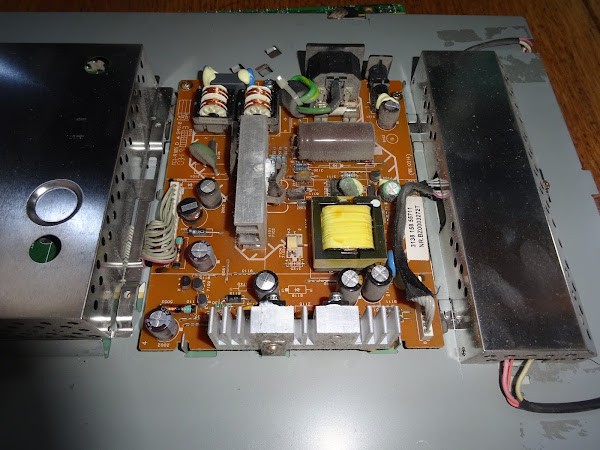
The middle board is the power supply, and it is connected by cables to the pod on the right, the backlight inverter, and the one of the left, the video processor.
These cables are fixed at one end, and have sockets at the other.
Guess which end is soldered in place?
Yes, that's right, the one on the power board, so to get that out, I have to remove both cans and unplug the connectors inside. That involves also undoing the jackposts on the VGA and DVI connectors. Not a great design.
The video processor board at least confirms the date code at around 2003. Not bad, it is still a good monitor with a bright clear picture, so it is worth a bit of frustration to fix.
These connectors are in a bit tight, but it's finally freed.
Now for the backlight inverter.
Damn.
I was pulling the cable hard enough to pull the plug out, not a massive force, but it ripped off the entire connector before it unplugged from the socket.
So that's two things to fix.
Luckily it was all the solder that broken, no damage to any of the tracks. I put it back with far too much solder, to make sure in case I have to disconnect it again.
And back to the original problem.
Same old thing with LCD TVs and lots of other consumer tech of the day such as DVD players etc.
The good old bulging caps with domed tops.
I spotted a couple, all of the CapXon brand (well known for being a bit CrapXon).
There were various other green and brown caps around the board which looked to be OK. Just the black and gold ones.
There were four of those, and two had failed, so I thought it best to replace all of the same brand and age.
The smallest is marked 820uF and reads as, well, it reads as a resistor.
The next 1000uF cap reads as half that, and quite a high resistance.
The two taller 1000uF caps actually read OK, but it is probably best to have replaced them anyway.
I use 105°C rated low ESR capacitors, these have generally proved good replacements.
I didn't have an 820uF 10V, so I went up to 1000uF here.
The 1000uF 16V is a direct replacement.
I didn't have any 1000uF 25V caps, but they were wired in parallel, so I replaced the pair of those with a single 2200uF 25V caps. That's OK, right?
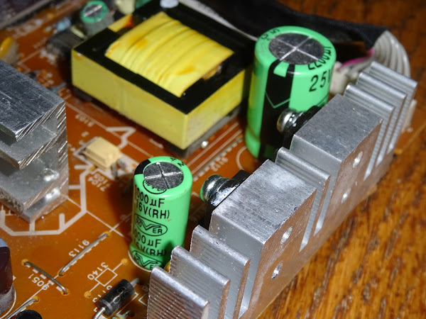
All the parts fitted, and you can see the permanently attached wires that made this job take twice as long as it needed to.


