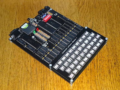
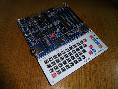
I think this will be the last in the series of previously Patreon exclusive posts on the development of the Minstrel 4D kits.
Loading from tape on the Jupiter Ace is achieved with fairly simply hardware.
I have isolated the relevant bits of the schematic, but it's probably easier if I redraw it.
There is a 3.5mm jack socket to connect to the "ear" output of a cassette record. That is filtered slightly and then fed via a permanently enabled buffer into the spare input on the keyboard read buffer. Why it is buffered is not clear, since the input stage on the 367 used to buffer the signal is identical to the input stage on the 367 used for the input port. That doesn't seem to help the signal in any way. There is no inversion, and no gain. (I do have a theory why this may have been done - see later)

The input stages are 74LS367, treat a signal greater than 0.8V as a logic 1. The keyboard is read via input port 0xFE (actually it is minimally decoded as "any odd numbered port", but only 0xFE is used by the standard ROM). The port is sampled repeatedly during loading and effectively digitises the analogue input signal. If your volume is set right, the high parts of the wave will generate a logic 1, and the low parts, a 0. This should recreate the signal which was generated during save, and can be turned back into a program.
I will not go into too much detail on the actual loading protocol. If you want to know more, there is an excellent reference here - http://www.jupiter-ace.co.uk/doc_AceTapeFormat.html
The inputs on the ZX80, ZX81 and ZX Spectrum are also very similar, just a singly different filter and no extra buffer.
When implementing this on the Minstrel 4th, I used a 74HC367, in keeping with the 74HC logic in the rest of that design. This was not ideal as the input threshold was a lot higher (2/3 VCC). To help this, I added a pullup resistor to bias the input signal around the centre of the rail, a signal which was higher would go into the 1 region, and the lower parts into the 0.
That worked fine with devices such as my trusty Sony TCM-818, or the cheap USB sound dongle I used for loading, but it didn't cope well with lower signals.
The Minstrel 2 kept the 74LS logic of the original ZX80, so performed better, but the Minstrel 3 also used 74HC logic and needed a higher signal.
I mainly used mine in combination with a modified TZXduino which output logic level signals (http://blog.tynemouthsoftware.co.uk/2019/12/tzxduino-master-tape-creator-update.html). I see some units available from ebay also have a switch to change the output from logic level to lower audio level.
Whilst the Minstrel 3 was still in production, I did try various options, including a transistor input buffer, to try to improve the loading, but none of them seemed to make sufficient difference to justify the extra parts and rerouting the board.
During the development of the Minstrel 3+ and the Minstrel 5 (neither of which reached production), I tried many different approaches.
These included some different transistor buffers, input stages using 74LS, 74LVC and 74HCT chips, Op Amps and comparators.
The next revision of Minstrel 3+ would have had a comparator circuit, but it needed 1% precision or better resistors to set the threshold, although ideally I would have used a voltage reference, but that would add more parts and more cost, so the resistor dividers were a better option.
I had a little box marked out to separate those 1% or 0.5% 5 band metal film parts from the rest of the board with the standard 5% 4 band carbon film resistors I prefer to use.
I revisited it again several times on the Minstrel 5, with various different circuits, Op Amps with hysteresis, Schmitt trigger inverters etc. etc. There are lots of Patreon posts documenting the progress thorough these if you want the full gory details.
And then one day, I was looking to change the microcontroller, ideally to a smaller one (and this is where the "sort of rubbish SPI" and "auto typing" came in).
Whilst I was picking the chip to use, I noticed that the ones I was looking at listed amongst their features analogue components such as Op Amps and voltage references and a comparator.
So I ended up creating the type of circuit I had designed above, but all within the microcontroller. More than that, the reference side of the analogue comparator could be set to a dedicated internal voltage reference, without the need for separate 8 pin chips or all the extra passive components (including no need for the 1% parts).
That reference could be set to anything from 0V to 2.048V in 256 steps, so that meant I would be able to offer a range of threshold voltages to suit lower level sources and high level up to logic level sources.
There was also the option to add hysteresis to the signal to give a cleaner edge. I was able to setup an output pin that could be set to drive the tape input port the Z80 sees with either the cleaned up logic level tape signal that came out of the analogue comparator, or the digital signal generated from "playing" tap files to load from internal memory or SD.
Perfect. Could this be the answer to the neat all in one solution I was after?
Yes, I think it was. The first time I set it up, it loaded straight away. I tried various input levels (using the volume control on the tape deck) and also various threshold levels, and it was working very well.
I have many assorted scope shots like these, I have redone them all recently as part of the testing of the Minstrel 4D. Once you have seen a few traces with wiggly lines at the top and square lines at the bottom, you will get the general idea and not need to see any more.
I was able to load from my PC motherboard sound for the first time, as that signal had been too low in the past.
The only thing I couldn't get to load was a Hi Fi separates cassette deck. I turned off as many of the signal processing and noise reduction features as I could but it was not outputting anything like the signal I was getting from the other decks with the same cassettes. I am sure it makes the music sound better, but for data it is no good. It was also at the extremes of the lower range.
It managed to load a few shorter programs, but with larger ones, it loaded the header correctly, but failed with "error 10" after a while. (Error 10 is a general catch-all error, basically, it failed to load)
The input circuit of the 4D was then back to something very similar to the Jupiter Ace, with just a simple filter. Instead of the seemingly unnecessary double buffering, here the signal very usefully passes through the clean up stages of microcontroller before reaching the same 74LS367 input buffer.
This has been tested a lot now, and I have been very pleased with the results. Since there was space, I added 5 different threshold voltages to the settings menu, that gives the user quite a range to cope with whatever sources they have.
All of this testing had been done with wav files, tapes created from wav files, tapes saved on Minstrel 4th and Minstrel 4D boards, and with the single commercial release for the Minstrel 4th (and Jupiter Ace), Tut Tut. (I am told there may be a second on the way very shortly)
The only unknown was how it would perform with vintage Jupiter Ace tapes. I put out an appeal on Twitter and was very grateful to receive a loan of 8 original Jupiter Ace tapes, all of which loaded without a problem.
It was as part of that testing that I can across one of the tapes, Atic Raid, which supported the Boldfield joystick.
Almost, but not quite, entirely a rip off of Atic Atac.
I had added a Kempston compatible port to the Minstrel 4D, I don't think their was ever one in the day, so it would only be supported by newly written software. However, the Boldfield joystick was essentially the same thing, just with the bits rearranged and on a different input address. With a few minor modifications, I changed the port to be Boldfield compatible, and was able to play the three available games that supported it (which was three more than a Kempston compatible interface would have had).
One of those was Valkyr, but that is quite a story, and deserves a post of it's own. (see the previous post "one game, so many changes" for the beginnings of this tale.)
I asked George Beckett, who wrote the Ace / Minstrel port of Tut Tut if he could add joystick support and he was happy to oblige, and also to allow the game to be built in, so Tut Tut is there to load directly from ROM, with joystick support ready to go.
I also patched Shiela Dixon's type in version of Grand Theft Cygnus to support joystick, that proved quite useful when I was testing typing in files from SD card.
When I was working on loading files from SD card, serial and ROM, it became clear that although faster than tape, it was still taking up to half a minute to load the largest files, and there was no indication of this other than the "Load" LED being lit. It was flashing along with the signal, but it looked to be on pretty much of the time.
I did consider various options, several LEDs that lit in sequence, like a light chaser or a Larson scanner, or even a bargraph or small LCD display.
I then though about using the same approach as the ZX Spectrum, and flashing the border of the screen. I wired that in to see what it looked like, and it was prefect.
It is at this point that I wonder if the plan for the Jupiter Ace was to have loading bars like this. There is that unnecessarily buffered signal. That is the perfect place to tap off the tape signal to generate those lines. If you take it at the input, you are doubling the load on the cassette recorder. You can't take it after the 74LS367 as that is just the data line and that will contain noise all the time. However, the extra buffer here is permanently active, so there is always a buffered, logic level tape data signal that could be wired to provide the border signal. If that had been done, the Ace would have had this form of loading lines with no additional parts required. I wonder if they backtracked on that idea in case it was another thing the could have been accused of "borrowing" from Sinclair?
Advertisements
Minstrel 4D
The Minstrel 4D kits are shipping now, you can order one from The Future Was 8 bit - SPECIAL OFFER - £15 off the Minstrel 4D and free shipping to the USA
https://www.thefuturewas8bit.com/minstrel4d.html
More info in a previous post:
http://blog.tynemouthsoftware.co.uk/2022/08/minstrel-4d-overview.html
Patreon
You can support me via Patreon, and get access to advance previews of posts like this and behind the scenes updates. These are often in more detail than I can fit in here, this post contains bits from several Patreon posts. This also includes access to my Patreon only Discord server for even more regular updates.
https://www.patreon.com/tynemouthsoftware


