Sunday, 12 January 2025

Why does the 1541 disk drive keep spinning?

This is a bit of a strange issue that came up during some recent testing.

It only happens if you load the PRG version of Rodman from a 1541 disk drive onto a VIC20 and run it immediately before the disk spins down.

When you do that, the disk activity light goes out, but the drive keeps spinning. The game runs fine, it is just the disk drive that behaves oddly.

It only if the drive is still spinning, there is not time to type R U N and press RETURN, so it is only automatic starts like the Penultimate Cartridge file browser. I also check it does the same thing if you have the BASIC 4 ROM if you do SHIFT + RUN/STOP and have Rodman as the first program on the disk. It both cases, the game starts immediately after loading.

I decided to wire up the logic analyser and have a look what is going on. Here I have the IEC bus side of Data, Clock and ATN, and the IO chip select line for the VIA chips.

This is the end of loading Rodman.

Looks OK to me.

For comparison, this is the end of loading Bertie the Ball, which does not leave the disk spinning.

I zoomed in a little closer for the screenshot, but it is doing the same thing. The three ATN pulses at the end to ask the drive to stop talking, close the file and release the bus.

Hmm. I was thinking it might be some weird edge case if the file was a multiple of some block size or off by 1 etc.

It was only when I zoomed out that I noticed a difference.

At some point, there is some IO activity and ATN gets asserted again and the drive thinks it is going to be asked to do something so keeps the rust spinning.

This is Bertie the Ball, you can see there is some IO activity, but the IEC lines are unchanged.

I think this might be a similar issue to that of the autofire on Bandits I saw previously.

The problem was with the port A output register on the userport VIA. The pins on there control IEC ATN line output, and are inputs for datasette sense, IEC clock and data and 4 of the 5 joystick directions (don't ask).

The PA7 output drives a 7406 inverter, which will assert the signal (pull the bus low) when PA7 is logic 1.

In Bandit's case, it was writing to that port as part of the initialisation and changing the value of bit 7 to 1. This asserted the ATN signal and because of a previous change to the other signals caused the drive to react, which meant the signals read from port A were different if a drive was connected.

I asked Misfit (the creator of Rodman) if he was writing to $9111, and he was good enough to check and found no writes to that address in his code (or the alternate version at $911F).

Odd.

He sent me the code, which consisted of 7 POKEs, setting up various registers on the two VIAs, but not including $9111.

   POKE(0x911C,0xFE);

   POKE(0x911E,0x7F);

   POKE(0x912E,0x7F);

   POKE(0x9112,0x00);

   POKE(0x9113,0x00);

   POKE(0x9122,0x00);

   POKE(0x9123,0x00);

I zoomed in to the point where ATN was asserted, and I could see those 7 POKEs (it's quite neat when you can actually visualise code happening)


You will see the spacing of those is not quite even. This again is visualisation of code. Due to clever ordering the statements, the compiler is able to optimise out several of the LDA statements where the same value is written to several addresses, and has already been loaded.

Looking at the trace, you can see it is the fifth POKE which causes the problem.

   POKE(0x9113,0x00);

Ah, of course. That is writing to the data direction register for port A, and setting all the pins as inputs.

The ATN out pin, controlled by bit 7, should be an output, as it directly driving the input of a 7406 inverter.

When bit 7 is set as an input, the input of the 7406 buffer will be floating, most lightly read as a 1. In practice, this depends on make, type and age of the VIA, how strong the pullups on the input pins are, and also on the make, type and age of the 7406 if it has an input pullup or what it will consider a logic 1.

This was first spotted by a colleague using Vice with "true drive sounds" on and it continued the "disk spinning" sound after the game had started.

I was testing here with a VIC20-CR and a Mini VIC and a 1541 drive.

The internal pullup in the 6522 most likely means that the ATN signal will be asserted. If this happens before the drive has spun down, it will keep the disk spinning as it thinks it is about to receive a new command.

It probably does this on an SD2IEC as well, but you wouldn't notice as there is no sound.

I tried a few more games, and noticed the same thing on Bolder Dan.

Here there are 20 pokes this time, the 4th one seems to assert clock and / or data, and the 13th asserts ATN.

How to fix this?

Ideally you would set bits 7 as an output and write 0 to those bit 7 in $9111. Both of which should already be the case, so the easiest fix is simply to remove the fifth POKE.

I am not sure this actually needs to be fixed, since it only affects someone using a Penultimate Cartridge and a 1541 disk drive to load a game which was never released on disk, and is already in the Penultimate Cartridge. Normal loads on any device are fine as the drive normally spins down before you have had time to type in R U N and press enter. 


Adverts

You can now get a ZX80 kit for $200.

Sorry, right price, wrong advert.

You can now get a Minstrel 2 kit for $200. 1980s pricing.

Or you can get a Minstrel 3 kit for $200

Patreon

You can support me via Patreon, and get access to advance previews of development logs on new projects and behind the scenes updates. These are often in more detail than I can fit in here, and some of these posts contain bits from several Patreon posts. This also includes access to my Patreon only Discord server for even more regular updates.

Sunday, 5 January 2025

Mini VIC Revisited Part 1

Way back in 2020, I started looking into producing a Mini VIC kit, along the same lines as the Mini PET. Something that was VIC20 compatible but built using modern W65Cxx and 74HC parts.

The trickiest part of that was finding a way to replace the VIC video (and sound) chip. I tried various options to get a microcontroller to be able to generate the video output.

These were looking promising, so I set about designing the Mini VIC board, at this stage with everything apart from the VIC chip replaced. The plan was this would be the test harness for the replacement video chip design.

I wasn't really happy with the way that turned out, I tried to do a few too many things, and it didn't work out as well as I would have liked. In order to save a few chips, I ended up complicating things with 4 way mux chips and things like that.

I also added configurable internal RAM. Whilst that was nice, it further complicated things. When that was enabled, it shouldn't enable the same zones in the cartridge slot etc. And at the end of the day, you will probably be running this with a Penultimate cartridge installed, so it would just be duplicating the 35K expansion anyway.

It sort of worked, but wasn't quite right.

At the time I put the project to one side, waiting until I had a better idea for generating the video.


Roll on 2024, and I have more ideas for generating the video output.

I did spend a while looking at a purely logic based VIC, the Maxi-VIC. Whilst this is viable, I think it worked out something like 80 - 100 logic chips, so was never going to be practical for something like this. (although never say never....)

There is promise of a drop in FPGA based VIC chip replacement, which would solve the problem.

(edit, there are now several FPGA versions in development)

I looked again at the design and decided to roll back several of the changes I had made and go for something closer to a VIC20-CR.

That meant going back to two ROM chips (still one better than the original three ROM chips), and just the standard 5.5K of RAM across two chips (again better than the 5 chips on the VIC20 CR or something like 500 on the 2 pin VIC20*).

* OK, it's 11. But it feels like 500

I was also not happy with my clock optimisation, timing is always a bit of an issue, so I again decided to roll back, at least for the moment.

I am not sure at this stage if I will stick with logic chips or if I will replace a whole load of those with a GAL chip or two. I need to build a revision with standard 74HC logic, at least to start with, I can then try out the GAL and see how viable that is.

Once I had moved things around, I had a lot of space left for whatever solution I come up with.

The timing is a bit complicated. The original 6502 has three clock pins, one input and two outputs.

There are 5-10ns gate delays between the outputs. Φ2 is a buffered version of Φ0, and Φ1 is an inverted version of Φ2.

Vintage systems would feed Φ0 from an oscillator (or sometimes video chip or ULA), and then the rest of the system would use the Φ2 output (or Φ1 for some reason on the BBC if I remember correctly).

The VIC20 was a little different, it has lots of clocks going on. The VIC chip has two clock inputs which must be complimentary versions of each other, and two clock outputs, although only one is used.

The 6502 is fed from an inverted version of one of those (which is what the unused clock output is meant to be ?), and the main system clocks S1 and S2 are generated from ORing Φ0 and Φ2. This gives a slightly longer pulse that either of those on their own.

The VIC20-CR further complicated things by also using Φ1 to gate the VIC R/W signal (handily using up four spare gates and a square inch of space from the schematic above).

For the final Mini VIC, I will be using the modern WDC W65C02S. This does things slightly differently. It still has the two clock outputs, but I found in testing on the early Mini PETs that there was some drift in these outputs over time and that was enough to make things unstable on longer term burn in tests. The datasheet states these should not be used.

I notice they have changed the naming, and what was Φ0 (in) is now Φ2 (in). When I disconnected the system clock of the Mini PET from Φ2 (out) and ran everything from one external clock fed to Φ2 (in), everything was suddenly rock solid stable, and it would run for days on end with no issues.

Trying to fit that into the VIC20's clock arrangement is going to be interesting. I have set the revised board up to the original timings, and with a jumper on pin 1*. I can fit either a 6502 or W65C02S on this board. That should allow me to investigate this further and work out the best implementation going forward.

(* pin 1 is a second ground pin on the 6502, but is frustratingly now an output on the W65C02S. Other differences just need a few extra pullup resistors, but that one is a deal breaker)

I managed to get quite far before I realised I had forgotten decoupling caps. I usually add one per chip, but I noticed there were very few on an actual VIC20, so I was going to see how it went with fewer. In the end I decided to leave space for the usual compliment, and maybe try only fitting some of them (or "Muntzing" a working board to see how many I can get away with).

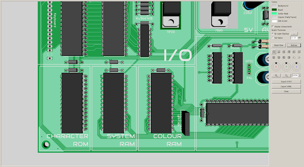
As always, I like to do a neat PCB layout. This one has lots of different busses, so I tried to arrange the parts to let them flow between the chips.

Also as usual, I routed myself into a corner in the middle of the board (I know what I mean), and had fun trying to sort out the routing for all the logic chips.

But I got there in the end. Not as elegant as I would like, but those may end up mostly replaced by a GAL or two which will make things simpler and neater.

GALs are great for dealing with all the address decoding, and replacing all those 74LS138s. And particularly the 74x133, a 13 input NAND gate, which is no longer in production in either it's 74LS or 74HC form.

I had to replace that with two 74HC21's and a 74HC10. (I was able to use the remaining parts elsewhere so not a complete disaster).

That's all routed now, it should be a drop in replacement for a VIC20 or VIC20-CR, with a few extra nice touches.

Made from all modern parts other than the glaring exception of the VIC chip, but hopefully an FPGA based replacement will drop from the skies at some point.


Adverts

You can now get a ZX80 kit for $200.

Sorry, right price, wrong advert.

You can now get a Minstrel 2 kit for $200. 1980s pricing.

Or you can get a Minstrel 3 kit for $200

Patreon

You can support me via Patreon, and get access to advance previews of development logs on new projects and behind the scenes updates. These are often in more detail than I can fit in here, and some of these posts contain bits from several Patreon posts. This also includes access to my Patreon only Discord server for even more regular updates.

Sunday, 29 December 2024

Coming up in 2025

Just a quick post to let you know about some of the things coming up in 2025.

Mini VIC

The first project likely to be finished is the Mini VIC.

I am currently tweaking the design to improve the video output (you might have noticed the recent deep dive into VIC20 video output circuitry)

The video output is looking better now, with a nice straight edge to the border (it is often very wibbly on a VIC20). There is still an issue with the colour RAM corruption (as demonstrated by the David Bowie tribute Black Star.).

Just needs a few mods.....

The plan is to complete that as a "needs a VIC chip" version in the new year. There are a few VIC chip replacements, which could either end up as a "you need to buy one of those" or be bundled in. Or potentially I might still get one of my own attempts at a VIC replacement working well enough. Either way, this is a solid test bed, as it has been already for the Penultimate +3.

Speaking of which..

Penultimate +3

The Penultimate +3 is available now.

I am currently working with a game developer on a new game that will make full use of the new features.

There will be a proper blog post to follow on that very soon, just waiting for things to settle down in the new year.

Speaking of which....

EU Shipping

Slight problem at the moment due to new GPSR rules that came into place on the 13th December. There seems to be a lot of confusion and conflicting information. It appears I can no longer ship things to the EU as I cannot afford to put in place all the documentation and representation required to be able to sell into the EU marketplace. I am hoping that will get sorted out in the new year.

My Tindie store remains open for shipping to the UK, US and the rest of the world, just not the EU at the moment (sorry, I didn't vote to cut us off from our friends over the channel).

Speaking of cutting yourself off from the rest of the world, we will see how changes in the US play out. It seems likely it is going to get more difficult, certainly more expensive, to get things into the US under the new administration.

What else?

Well, following hot on the heels of the Mini VIC will be the Mini PET II. This is a redesign of the Mini PET to get around two main parts that are now out of production.

But it got a bit more complicated than that.

Just a test bed for the moment. I have a proper PCB made up, but I am trying not to work on too many things at once, and concentrating on the Mini VIC for the moment.

You might notice one of the boards I "borrowed" for the development process was a "Project ORAC" board.

ORAC

This was the beginning of an Oric 1 / Oric Atmos clone. I also have a new board for that with a few tweaks. That will follow after the Mini PET II.

Z80 Projects

After somewhat optimistically buying a lifetime supply of Z80s I have been a little disappointed to have only sold a few of them as part of the Minstrel 2 and 3 kits. I guess everyone who wanted one of them either cannot afford one or already had one.

So onto new Z80 based projects. Several are in the works. Not sure it is a good idea to continue with the ZX Spectrum compatible machine just now, but there are lots of other things that are now back on the table now I have lots of Z80s to use.

There are lots of development log posts on the upcoming Mini VIC and Mini PET II on my Patreon, I will start to post these on here once they are finished, until then, check out my Patreon if you want to know more.

2024 didn't quite go to plan, let's hope 2025 is full of 8-bit goodness.


Advertisements

Minstrel 2 and 3 kits are available from my Tindie store.

Versions are available for ZX81 case:

Or standalone with keyboard:

And also Minstrel 3 with ZXpand microSD card interface:

I have listed the Minstrel 2 and Minstrel 3 PCBs with and without keyboards or overlays on Tindie. Just in case you want to source your own parts and don't like the ease and simplicity of having them all supplied in neat little bags and a foam pad with all the ICs in order.

I am in the process of moving things over there from my SellMyRetro store, so if there is anything that you want, let me know and I'll add it.

I have recently added lots of PET repair and upgrade parts, more to follow.

Bluesky

For those interested in such things, I can now be found on Bluesky.

I am almost at 500 followers, a fraction of what I had on Twitter, but a whole load more interaction and a nicer environment.

Patreon

You can support me via Patreon, and get access to advance previews of development logs on new projects and behind the scenes updates. These are often in more detail than I can fit in here, and some of these posts contain bits from several Patreon posts. This also includes access to my Patreon only Discord server for even more regular updates.