
This is a first. A Mini PET 40/80D that is no longer working.

I don't think TFW8b has had many support messages about the 40/80D. Most were technical enquiries about it's suitability.
- No, it won't work with a Super PET.
- No, you can't use it with a Commodore 64 keyboard.
- Yes, I know The 8 Big Guy did that in a video.
This was the first user to actually have a problem.
The board had arrived, been installed in a PET 2001, powered on and worked. Power on chirp, READY prompt on the screen etc.
Great, that's what it is meant to do.

(yes, that is my PET 2001, I didn't have a photo of the user's one, call this an artists impression)
But then, when they went to turn it on a second time, it was dead. There were some LEDs lit on, but no chirp, no video?
The owner was helpful enough to try some different power supply and monitor options to see if we could narrow it down, but in the end, the best option seemed to be to send it back to me to investigate.
It arrived fairly quickly, the original packaging surviving a second trans-Atlantic flight, and the board looked fine.

No obvious physical damage, nothing to suggest anything wrong.
I powered it on from a 9V DC bench supply, and it drew about 400mA, which is high for one of these boards, they are normally around 150mA.
The LEDs near the SD socket flashed at power on as normal, so that was alright.
The power LED was on, as were the two datasette motors LEDs, but the Ready LED was off.

Normally, a few seconds after power on, the Ready LED goes on, and the motor LEDs are turned off as the PET boots up.
That wasn't happening.
Poking around looking at voltages, the 9V input was there, dropped slightly by the polarity protection diode.
The 3.3V rail was there, and the the things like the SD card LEDs were behaving normally.
The two 6V motor supplies were enabled and at the correct voltage.
The 5V rail was reading 0.7V.
Ah, there's ya problem.
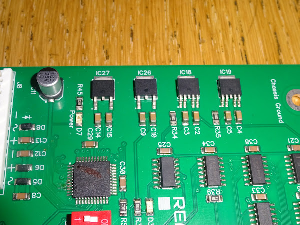
The 5V regulator (IC26) was getting warm.
I powered off and checked for shorts, and yes, the 5V rail to ground was reading a bit over 1 ohm. So there was a short somewhere.

I checked around again for anything obvious.
I also probed around, trying to find a spot where the resistance was lower, but it all seemed to read about the same, and went down as you were reading it, presumably because of all the capacitance on the rail.

Difficult to track something like that down without being able to remove chips, and these are all surface mount.
Well, there were two EPROM chips in sockets.
I removed those.
It wasn't them.

I though I would quickly try the fingertip test to see if any of the chips were getting hot.
I didn't want to damage the 5V regulator by running with a short any longer, so I powered the 5V rail direct from the bench supply at 5V.
Current limiting again kicked in, but none of the chips were getting noticeably hot yet, so I kept winding up the current bit by bit until at about 700mA I noticed one of the chips was getting hot.
It wasn't clear at first, but once the current had been increased, it became clear that the 74HC86 was burning hot and the others were just warm due to conducted heat.
The 74HC86 is the third one down, next to C41, for those playing along at home.

I was fairly confident that was the problem, so I removed it and fitted a new 74HC86.
It I wasn't sure, I would have removed it and checked for shorts again, but I had an idea why it might have failed, so just went for it.

I plugged it back into the power (and was confident enough to also plug in a monitor), and powered it on.
There was a chirp.
There as a ready LED.

There was a READY prompt. (one day I will get better at taking photos of screens, surely I have to some time, right?)

Success.
All down to this one pesky chip.

Self test ran for several hours, and several power cycles, with no problems, and the current as a respectable 150mA.

But why did it fail?
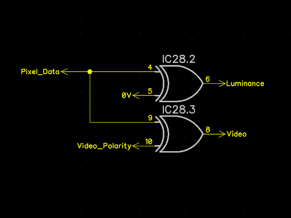
Well, only two gates on that chip are used (don't worry, the inputs of the other two are tied to ground). Of the two used gates, one drives the video signal into the composite video mixer amplifier, and the other drives the video signal to the PET monitor.
This is the same circuit as used in hundreds of Mini PETs, Mini PET 40/80s and Mini PET 40/80Ds, and there have been no 74HC86 failures as far as I know with any of those.
It is also essentially the same output stage as the original PET, although that had an extra pull up resistor added as the 74xx series could only really drive low, so that boosts the internal pull up on the high side.

My theory is that there must have been some high voltage pulse on the video line from the monitor that fried the 74HC86 chip on the 40/80D.
The PET monitors are pretty basic, so it is possible that some fault in the monitor is causing high voltage on that line. When I say high voltage, I mean "anything above 5V". There are 12V, 85V and 400V rails in there, any of which could kill a poor little logic chip.
The obvious one is in the input stage, this is a slightly odd level shifter.

When the video input is high, CR1 is reverse biased, so there is no current flow through it. 12V goes via R1 through two diodes CR2 and CR3 and the transistor base emitter junction, which is effectively another diode. That should mean the point at the bottom of R1 should be at about around 1.8V, and Q1 will be conducting, and further down the line, an electron bean will strike some phosphor and a pixel will glow green (or white depending on the phosphor).
When the video input is low, CR1 conducts, and brings the end of R1 down to about 0.6V. This will turn Q1 off, and also stop the flow of electrons, and the pixel will be black.
If CR1 has failed short, or is leaking, it could let the 12V down the line to the video connector and to the 74HC86, and even via a resistor, could damage it. (I don't have the users monitor here to verify or repair this, it is just a theory)
The design is much the same with the 12" PET monitor, other than the polarity is reversed somewhere along the line, and the input voltage is now 18V (marked as E18 for some reason best known to whomever drew the schematic).

So that's my guess what happened. A short or leaky CR1/D201 fried the 74HC86. I wouldn't be surprised if the same fault fried the 7486 on the PET motherboard that originally drove that monitor.
The repaired board is ready to go back, but I am worried the same fault could fry the new chip as well.
I am wondering about adding a pair of clamping diodes on that pin, to protect the chip.

There was never anything like that on the PET video connectors, but maybe a good idea in this case.

Commodore added that arrangement of diodes to later C64 and early plus/4 boards, a factory fitted mod to protect the inputs on the IEC port (presumably after all the 7406's started dying). They were also added to the C64C and later versions of the plus/4 schematic (but not the Commodore 16).
I added clamping diodes to all three signals on the video connector (the other three pins are ground). The two sync signals come from the microcontroller, and should already have internal protection with a similar arrangement of diodes, but this is just extra protection.

And just to reiterate, I don't think anyone else needs to fit these, it is only this particular case of a faulty monitor.
It is always tricky with this sort of "here is a one in a million weird fault you will probably never see again" fault. They inevitably lead to people saying "I replaced the chips you said, but it didn't fix it".
Fix what? did you have that same one in a million fault? "no mine was different, but I thought I would fix it......"
Advertisements
Mini PET 40/80D

There are one or two Mini PET 40/80D boards still available from The Future Was 8 bit:
More info in a previous post:
http://blog.tynemouthsoftware.co.uk/2022/03/the-mini-pet-4080d.html
Mini PETs
The original 40 column Mini PETs are available from my SellMyRetro store in both B (internal green boards) and A (stand alone white boards) versions.
Mini PET B

The B version is designed as a drop in replacement for the PET mainboard.
This is available in built and tested, full kit and partial kit form:
Mini PET A

The Mini PET V1.48A is a standalone version, also available in built and tested, and partial kit form (let me know if there is interest in a full Mini PET with keyboard kit):
As well as a choice of matching keyboards PCBs.
Patreon
You can support me via Patreon, and get access to advance previews of posts like this and behind the scenes updates. These are often in more detail than I can fit in here. This also includes access to my Patreon only Discord server for even more regular updates.
https://www.patreon.com/tynemouthsoftware
