
I have added composite video outputs to many Atari 2600 VCS consoles, and covered those in previous blog posts about the 2600 Woody and 2600 Jr.

The first ones of these I did, I built the buffer circuit on stripboard.

Soon after that, I designed a PCB to make that process easier.

A smaller version of that went into production at The Future Was 8 bit, and I used those boards for many conversions, include ZX81, TS1000, Spectrum, TV Pong games and of course more 2600s.

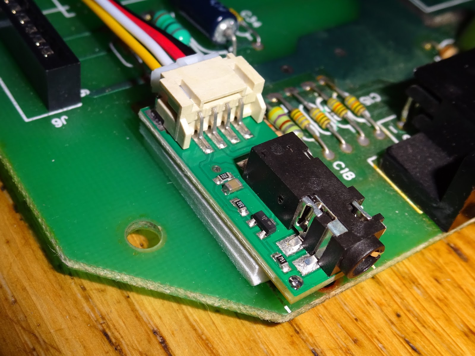
These made it easier than having to build up the stripboard versions, but I still had to source and prepare the AV leads and the wire links. On a recent mod, I tried fitting a socket to the input side of the board and used a pre-wired 4 way cable for the connections.

That did seem to make things easier, so I looked around for a similarly pre-wired AV lead, but couldn't find anything suitable. What I did find was a lot of 3.5mm 4 pole jack to three phono plug leads. So I added a 3.5mm jack socket to the other end of the board and used those.

The result is a board with a 4 pin connector and one end and the jack socket at the other end. This should make it a lot easier to do these sort of modifications.

As before, the smaller, neater versions of these are available from
The Future Was 8 bit.
I am going to show you how to use these to modify various Atari 2600 systems,
but first I am going to cover a bit of the theory behind what parts should be
removed and how to locate them. By all means skip to the relevant section
below if you prefer.
Theory
The circuit is basically the same throughout all the models of 2600 from the 'heavy' sixer through to the 2600 Junior. The part numbers and values do change, so don't blindly follow any guide which just lists part numbers.
Let me just say that again, in big letters.
Part numbers do change between revisions, so don't blindly follow any guide which just lists part numbers or positions unless your board is identical to the one shown.
This is an example of the circuit, ignore the part numbers unless you happen to be using the matching board. The important thing is to identify the parts in the schematic and relate that the to parts on the board.

This circuit is an oscillator which adds the audio signal from the TIA into the combined video signal that is fed to the modulator. When doing these modifications, it is better to disable this behaviour, so you do not get any noise on the video caused by the audio oscillator section.

You will see differing opinions on which parts need to be removed. These are the parts I normally remove. Removing the resistor on the left separates the audio output from the video circuitry. The resistor on the right separates the video circuitry from the audio oscillator, and removing the inductor (the one with the big red coil) and transistor will disable the oscillator.

With those bits removed, you can see how the separation has been achieved. It also leaves suitable points to pick up the signals we need for the AV output.

The colours used are as follows:
- Black is a ground connection (available at various points around the board)
- Red is 5V. this can usually be tapped from the place where the variable inductor was
- White is the audio out, which can be tapped where the resistor was removed
- Yellow is the video out, which can be tapped from the other resistor position
The other thing which needs to be removed is the modulator itself, including the daughter board if one is fitted.

The following are examples of three common Atari 2600 PAL boards. If your board does not match any of those, you should be able to work out the appropriate parts by matching them up the the schematic above.
Atari 2600 "Woody" 6 switch PAL
The first one is the "Woody" style 6 switch Atari 2600 VCS. This has two boards, one with the switches and the modulator on, and one inside a diecast box with all the interesting circuitry on.

Inside the box, the relevant bits are on the right hand side of the board.

Here they are labelled R209, R216, L201 and Q202.

With those removed, the appropriate signals can be picked up from the pads they used to occupy.
The audio is tapped from the right hand side of R209, Video from the right of R216, 5V from the bottom of L201, and 0V from a pad to the side of C238.

A slightly better angle on a different board shows the point where 0V is connected to the spare pad of C238.

The wires can be fed under the cartridge socket and out of the metal box.

The buffer board can be placed somewhere convenient in the case, I used a self adhesive foam pad to stick it in place, and fed the video cable out the hole in the back where the TV cable used to go.

Atari 2600 "Woody" 4 switch PAL
The four switch version has a similar case to the six switch, but inside there is a single board. Unlike all the others, this does not have the 4050 buffers in the video section, but does add a 555 timer reset circuit. Later boards reversed both of these changes.

The video section is on the bottom right of the board.

Here, the parts removed are R209, R207, Q201, L201 and the RF modulator. In this case, I connected the wires to the 5 pin header next to the modulator, but you could pick up the signals from the component pads as before if you prefer.

Place the board at a convenient point in the case. I don't have a case for this one (I use it for testing), so I mounted the board at the back where the channel switch would have been on NTSC models.

Atari 2600 Junior PAL
The 2600 Jr is also a single board construction, with all the interesting bits under a metal screen.

With that removed, it has a similar layout to the 4 switch board.

The video parts are again bottom right of the board.
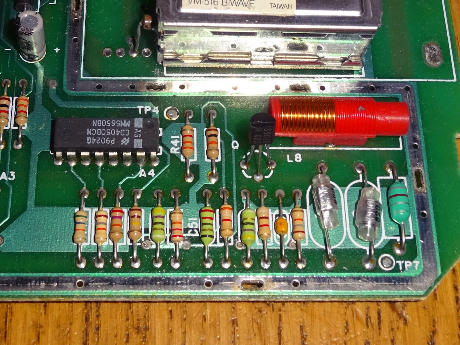
The parts to be removed are Q4, L8, R48, R56 and the modulator.

This time, I connected the wires on the bottom of the board, and soldered to the points shown.

The wires all go through a hole that was under the modulator.

The video buffer board can then be fitted where the phono connector was for the original TV out, raised up on a couple of foam pads.
This gives a neat mod and doesn't interfere when the screen is replaced.

The 3.5mm jack cable can now be plugged in where the old video lead would have plugged in, with no modification to the case required.

All back together, and time for some more testing I think.

Oh, I suppose I should put in a screenshot.

Looks good to me.
Update:
New blog post on a 2600 Junior without a modulator box:

The 'deluxe' composite video mod kits are available from The Future Was 8 bit.
