Sunday, 29 December 2024

Coming up in 2025

Just a quick post to let you know about some of the things coming up in 2025.

Mini VIC

The first project likely to be finished is the Mini VIC.

I am currently tweaking the design to improve the video output (you might have noticed the recent deep dive into VIC20 video output circuitry)

The video output is looking better now, with a nice straight edge to the border (it is often very wibbly on a VIC20). There is still an issue with the colour RAM corruption (as demonstrated by the David Bowie tribute Black Star.).

Just needs a few mods.....

The plan is to complete that as a "needs a VIC chip" version in the new year. There are a few VIC chip replacements, which could either end up as a "you need to buy one of those" or be bundled in. Or potentially I might still get one of my own attempts at a VIC replacement working well enough. Either way, this is a solid test bed, as it has been already for the Penultimate +3.

Speaking of which..

Penultimate +3

The Penultimate +3 is available now.

I am currently working with a game developer on a new game that will make full use of the new features.

There will be a proper blog post to follow on that very soon, just waiting for things to settle down in the new year.

Speaking of which....

EU Shipping

Slight problem at the moment due to new GPSR rules that came into place on the 13th December. There seems to be a lot of confusion and conflicting information. It appears I can no longer ship things to the EU as I cannot afford to put in place all the documentation and representation required to be able to sell into the EU marketplace. I am hoping that will get sorted out in the new year.

My Tindie store remains open for shipping to the UK, US and the rest of the world, just not the EU at the moment (sorry, I didn't vote to cut us off from our friends over the channel).

Speaking of cutting yourself off from the rest of the world, we will see how changes in the US play out. It seems likely it is going to get more difficult, certainly more expensive, to get things into the US under the new administration.

What else?

Well, following hot on the heels of the Mini VIC will be the Mini PET II. This is a redesign of the Mini PET to get around two main parts that are now out of production.

But it got a bit more complicated than that.

Just a test bed for the moment. I have a proper PCB made up, but I am trying not to work on too many things at once, and concentrating on the Mini VIC for the moment.

You might notice one of the boards I "borrowed" for the development process was a "Project ORAC" board.

ORAC

This was the beginning of an Oric 1 / Oric Atmos clone. I also have a new board for that with a few tweaks. That will follow after the Mini PET II.

Z80 Projects

After somewhat optimistically buying a lifetime supply of Z80s I have been a little disappointed to have only sold a few of them as part of the Minstrel 2 and 3 kits. I guess everyone who wanted one of them either cannot afford one or already had one.

So onto new Z80 based projects. Several are in the works. Not sure it is a good idea to continue with the ZX Spectrum compatible machine just now, but there are lots of other things that are now back on the table now I have lots of Z80s to use.

There are lots of development log posts on the upcoming Mini VIC and Mini PET II on my Patreon, I will start to post these on here once they are finished, until then, check out my Patreon if you want to know more.

2024 didn't quite go to plan, let's hope 2025 is full of 8-bit goodness.


Advertisements

Minstrel 2 and 3 kits are available from my Tindie store.

Versions are available for ZX81 case:

Or standalone with keyboard:

And also Minstrel 3 with ZXpand microSD card interface:

I have listed the Minstrel 2 and Minstrel 3 PCBs with and without keyboards or overlays on Tindie. Just in case you want to source your own parts and don't like the ease and simplicity of having them all supplied in neat little bags and a foam pad with all the ICs in order.

I am in the process of moving things over there from my SellMyRetro store, so if there is anything that you want, let me know and I'll add it.

I have recently added lots of PET repair and upgrade parts, more to follow.

Bluesky

For those interested in such things, I can now be found on Bluesky.

I am almost at 500 followers, a fraction of what I had on Twitter, but a whole load more interaction and a nicer environment.

Patreon

You can support me via Patreon, and get access to advance previews of development logs on new projects and behind the scenes updates. These are often in more detail than I can fit in here, and some of these posts contain bits from several Patreon posts. This also includes access to my Patreon only Discord server for even more regular updates.

Sunday, 22 December 2024

Reading the joystick port from VIC20 BASIC

The post I wrote on fixing Autofire in VIC20 Bandits (and Multitron) was originally much longer. Patreon supporters got to see the full version in October, but when I came to post it here on the blog in November, I thought it was too long, so I cut some bits out. I now present the "deleted and extended scenes" from that post.

Let's start with a bit of VIC20 BASIC.

Reading a joystick on a VIC20 from BASIC

To read port A of first 6522 VIA chip in the VIC20, you can use the BASIC command

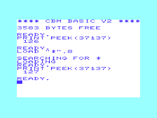
    PRINT PEEK(37137)

You can write a very simple program to repeatedly print that out

    10 PRINT PEEK(37137)

    20 GOTO 10

If you take a standard VIC20 with nothing attached and do that you will get a value of 126 all the time.

If you have a joystick plugged in, you will still read 126.

If you press fire, the value will change to 94.

If you move up, the value will change to 122.

If you move down, the value will change to 118.

If you move left, the value will change to 110.

If you move right, the value will still read 126.

That's a bit of an unfortunate quirk of the VIC20. For some inexplicable reason, the joystick right input is on a different port, on a different chip, so you have to do

    PRINT PEEK(37152)

Normally that will read 247.

If you move right, the value will still read 247.

But I thought you said....

Yeah, another quirk of the VIC20. That port is normally all outputs, driving the keyboard columns. In order to read it, you have to set it to an input first.

Really? but that's very inconvenient. Yeah, well, I didn't design it.

Instead you need to do something like this

    10 POKE 37154, 127 : PRINT PEEK(37152) : POKE 37154, 255

    20 GOTO 10

That will set the relevant pin to an input, read the value, then set it back to an output so it will not mess up the keyboard scan routine.

Now if you run that it will normally print 247.

If you move right, the value will change to 119.

(although ideally you would not have the PRINT routine there, just read to a value to reduce the time where the pin is not an output)

Given that information, you could write a simple program that reads those ports, and compares against those values.

    IF PEEK(37137) = 94 THEN PRINT "fire!"

However, there are a few problem. If you move up and press fire at the same time, you get a different value, 90, so the test would fail.

A better way is to test the individual bits, so

    IF (32 AND PEEK(37137))=0 THEN PRINT "fire!"

(it is never ideal doing bitwise work in decimal, it is much easier to see in hex or binary, but that's what we're stuck with in BASIC).

10 A = PEEK (37151)

20 POKE 37154,127 : B = PEEK (37152) : POKE 37154,255

30 IF (A AND 4) = 0 THEN PRINT "up"

40 IF (A AND 8) = 0 THEN PRINT "down"

50 IF (A AND 16) = 0 THEN PRINT "left"

60 IF (B AND 128) = 0 THEN PRINT "right"

70 IF (A AND 32) = 0 THEN PRINT "fire"

80 GOTO 10

That seems to work.

But what about the other bits?

There are also some other issues with just comparing values.

If you have a datasette plugged in, the value of 37137 will still read 126.

If you have left the play key pressed after loading, the value will now read 62.

All your comparisons by value will now be broken, bitwise tests will be fine.

The obviously causes an issue for some games, which have a "PLEASE STOP TAPE" message at the start of the game (rather than changing the tests to cope with that)

Something else that affects the value is the IEC bus.

If you have a IEC drive plugged in, the value of 37137 will still read 126 at power on.

If you have accessed that drive, it will now read 127.

Any developers working on a purely tape based system may not have known that.

There was also this long section that was cut where I worked through what was happening in the game Bandits.

There is one more game on the cartridge which has this autofire issue, but I haven't been able to fix that before. Time to have another go.

Fixing Bandits

I wonder if I can fix Bandits now? That seems to just autofire all the time, it does move correctly, but fire is stuck on.

The issue is the same, although the implementation is a lot more complicated.

   lda $9111

   asl

   asl

   asl

   bcs label_b410

   and #$ef

And it goes on

label_b410

   asl $9120

   ror

   ora #$04

OK, I worked through this to find out what is going on. The ASL is arithmetic shift left. That moves the state of the fire button out into the carry. That gets rid of the IEC ATN and cassette sense in the process, but leave the IEC clock and data in the mix (now moved to bits 3 and 4)

It can test the fire status by checking the carry bit. If it is clear (i.e. if fire button pressed), it clears a different bit with an AND instruction. It clears bit 4, and in future testing, that is the bit it now uses for testing fire. (why it does this I don't know, maybe they just wanted the directions together?)

After that it reads VIA#2 Port B and shifts bit 7 of that into carry. The ROR is rotate right, that rolls the carry (joystick right) into the accumulator.

Finally it ORs this with 04, which forces bit 2 high.

The final upshot of all that is the accumulator now contains joystick right, joystick left, joystick down, joystick up, and the reposition joystick fire. It then saves this and uses it for comparisons.

        C 7 6 5 4 3 2 1 0

Read   x A C F L D U d c

         ASL    A C F L D U d c 0

         ASL    C F L D U d c 0 0

         ASL    F L D U d c 0 0 0

         AND EF F L D U f c 0 0 0   if fire f = 0, otherwise d       

       ASL 9120 R L D U f c 0 0 0

         ROR    0 R L D U f c 0 0

         ORA 04 0 R L D U f 1 0 0

On a normal VIC20 with no IEC device attached, that works fine. It assumes that the value of bit 4 part way through shuffling is going to be a 1. It then sets it to 0 if fire is pressed. However, if the value of that pin is already 0, then it will think fire is pressed when it isn't.

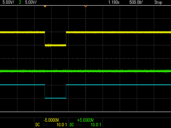
That bit happens to contain the value read from the IEC data pin, the top trace in yellow as before.

That is how it looks if you have no IEC device connected. The dips are when the chip is in reset. The drive pins become inputs, and the inputs to the 7406 buffers float high and assert the signals. After reset, the pins are set as outputs. Data and ATN are released, but clock stays asserted as that is the default state for the VIC20. Basically it is putting it's towel down on the deckchair and saying "if anyone is going to talk around here, it is going to be me".

If there is an IEC device present, it sees that and responds appropriately by asserting data to say it is ready to receive.

Bandits seems to interpret that as fire being pressed.

The autofire can score quite well just sitting there, but ideally you would have control.

As with the other games you can avoid this by not having an IEC device attached.

The odd thing with Bandits, is you can also"fix" the problem by pressing the drive reset button. That's unusual, I don't think any of the other games were helped by this.

I tried all sorts of things, including resetting the drive via software before launching the game, but always when it started it would it would end up with the data line held low.

I finally got to the bottom of why, and it wasn't part of the code above that reads the port, it was earlier on in the initialisation........

The story continues in the main post where I then went on to fix the problems in Multitron and Bandits.


Advertisements

The patched versions of Bandits and Multitron are included in the new Penultimate +3 version which also has a built in SD2IEC drive.


Minstrel 2 and 3 kits and PET repair parts are available from my Tindie store..

I will slowly be moving things over there from my SellMyRetro store, so if there is anything that you want, let me know and I'll add it.


Patreon

You can support me via Patreon, and get access to advance previews of posts like this and behind the scenes updates. This also includes access to my Patreon only Discord server for even more regular updates.

Sunday, 15 December 2024

VIC20 / VIC-1001 Video output

The eagle eyed amongst you may have noticed a bodge board near the VIC chip on the early VIC-20 board I repaired in the last post (http://blog.tynemouthsoftware.co.uk/2024/12/vic20-vic-1001-repair.html)

This is presumably a factory modification, the board has a Commodore part number (321461)

But what does it do?

Well, as I have been working on the Mini VIC, I have reached the conclusion that the video output on the VIC20 is a bit like the switching regulator in the ZX Spectrum. It changes with every revision of the board, sometimes mid revision with factory mods applied to production units, and it is still rubbish even after all of that, they never did get it right.

As far as I know all the VIC chips are essentially the same. However the outputs vary quite a bit from chip to chip, even in the same batch. Maybe in an attempt to deal with this the VIC20 video output circuitry changed significantly over time.

6560-101 is the NTSC VIC chip and 6561-101 is for PAL (other suffixes are for different variants of the optional pins as described in the 6560 datasheet - I don't think I have ever seen one that isn't the standard -101 version, other than a 6561E in one of the later photos which is also the same).

This appears to be the third version. The first was on the actual Japanese VIC-1001.

VIC-1001

Pictures of the early boards are taken from the excellent Commodore VIC 20: A Visual History by Giacomo M. Vernoni (used with permission)

This is presumably the very first revision. 1980 date code. There are more board revisions than their are schematics online for the VIC20, and some of the boards don't match the schematics anyway, so I have reverse engineered these to see what is going on.

Notice the track break under the 47Ω resistor? And two vertical resistors to the sides of the capacitor in the middle that are using the pads of a single horizontal resistor.

This is the published version of the VIC-1001 schematic, drawn in a different style to all the later VIC20 schematics.

This is my best guess at what is actually going on. The 75Ω resistor R30 does not seem to be present and there is an extra 470Ω resistor that I am not sure what that is doing. But it does include the two biasing resistors that were fitted vertically in that place of what looks to have been a single pullup resistor.

The circuitry here has to do a few things. The video output of the VIC chip is in two parts. One pin outputs sync and luminance signals, basically black and white composite video as would be generated by a ZX81 or Mini PET etc. It is difficult to get a clean version of that as it picks up interference from the chrominance even when disconnected.

The second signal, the bottom trace, is that chrominance signal, high frequency colour information.

The VIC is internally S-Video, although that standard did not exist when the VIC20 was born. Normally the two signals are combined almost immediately they leave the chip.

It is possible to get an S-Video output from a VIC 20. It is a simple mod, but is only worth doing if you have a good S-Video monitor or capture gear. I have seen quite a few things which claim to have S-Video input, but all the do is merge the signals to get composite and display that. I have been meaning to convert one for a while, but I don't have a good S-Video display in my normal setup.

To generate composite video, these need to be combined.

To complicate things, the levels need to be adjusted here and there to get the combined signal at the correct level to drive a monitor input. (since those levels change from VIC chip to VIC chip)

A further complication is the sync and luminance output is open collector. Meaning it drives to ground only, so needs a pullup resistor to bring it up to the correct level.

This version combines the two signals directly with a 100pF capacitor (at least according to the schematic, although that also shows a 220pF capacitor to ground which does not appear to be present on this board revision).

The pullup is controlled by the variable resistor, giving a range of 0-5V for the pullup.

That would be adjusted to get the 1V peak-peak video signal on pin 4 of the AV connector.

On these early boards, there was also a second video output, higher voltage, on pin 5.

The combined and pulled up signal is then decoupled by a 22µF capacitor and biased by a pair of resistors. These are mounted vertically, so I can't see the values. I will assume they are as per the schematic and later board revisions, 3.9KΩ and 8.2kΩ. This is buffered by a simple emitter follower transistor amplifier and output across the two output resistors.(Update, the schematic shows 6.2kΩ rather than 8.2kΩ, but that may be a typo since 62 is not a standard E12 value, but 82 is.)

The audio is buffered by another simple emitter follower and fed to the AV jack (pin 3).

The VIC20 does not have an onboard RF modulator, it came with a one in an external box which plugged into the 5 pin AV jack. Power for that is provided on pin 1. On this board, that is derived from the 9V supply, via a 180Ω resistor and marked as "6V".

Later VICs changed almost all of that.

First NTSC VIC20

The next revision is the first official VIC 20, the board which looked very much like the VIC-1001, but with a few minor changes.

Again, I have reverse engineered that as best as I can as I have not seen a schematic that matches it.

This has two jumper pads in place of the drilled out trace. The 470Ω resistor is gone, and the 220pF that was on the VIC-1001 schematic has reappeared. There is a new 75Ω resistor added between the level adjustment potentiometer and composite video signal.

The "6V" has been replaced by a direct connection to 5V, see the wire link to the right of the VIC chip. All future VICs just had 5V direct like this. Even though the manual continued to say 6V I think all of the production VIC20 boards were 5V.

Second NTSC VIC20

That is the version of PCB that is used on the VIC20 board I repaired, but it had various modifications.

It just about matches this photo from the book, so I presume this became a standard modification, although the one I worked on had no silk screen.

Some parts have been removed, some bypassed, and the extra board added with a transistor and some passive components.

I presumed this must be additional buffering or an amplification stage, but both were wrong.

The new board is actually working as a voltage regulator. The potentiometer now feeds the mod board and creates a regulated and smoothed supply to pullup the sync and luma output.

The 220pF capacitor to ground is gone again, and so is the decoupling capacitor and biasing resistors, so the output is just an emitter follower to buffer the signal.

I guess this smoothed supply was an attempt to reduce noise, and I have to say this was one of the nicest pictures I have seen from an NTSC VIC, with a clean straight line between the border and background, rather than the usual ripply line.

This one does not suffer from the usual mushy colours around the white lines either, nice and crisp, and strong colours as well.

It is also the first one that seems to have the levels right on the output.

NTSC 2 pin VIC20

Things seemed to change radically for the NTSC 2 pin VIC20 with all the mods for FCC approval.

There were a few variations. This one has a different version of the voltage regulator mod board above integrated into the design. The capacitor is now on the input rather than the output. Not sure I agree with that, maybe a small capacitor on the input as that should be stable, and the larger one on the output? Even a zener on the input to fix the voltage?

Over versions removed that regulator altogether and just used a simple pullup resistor.

Most of these had two potentiometers, one to set the signal level buy adjusting a tap on the input signal rather than adjusting the pullup level. The second pot sets the black level.

The two output signals are generated differently, now using an LC network instead of a potential divider.

(also note the PN2222, the favourite transistor of Commodore at the time, used everywhere. The VIC-1001 used three different transistors types)

PAL 2 pin VIC20


The first PAL version had more changes (and the extra clock divider on the right). Some values changed and parts were omitted, including the can itself.

VIC20 CR

And things changed again for the cost reduced VIC20-CR board.

This was the simplest (and I think worst) version.

Just a simple pullup resistor on the output. Then the level setting pot. Decoupled and biased and then the emitter follower output to both pins tied together on the output. No more high and low variants.

I am not sure if it was just a PAL change, or if later NTSC boards were the same, but most of the VIC20-CR boards I have seen have the capacitor that adds the chrominance to the luminance at 45° on the board, actually connected to the output of the level setting potentiometer rather than it's input. Which is why most PAL VIC20-CR boards you will see have far too much chrominance, overloading the luminance signal.

I have not seen a version of the schematic with this mod, so I made one.

Update

It appears the 321461 Mod Board was available in kit form, presumably to service centers. Pictures of this board and scans thanks to Commodore Z.

Looks to be the same board that was fitted to the VIC20 I repaired.

There are fitting instructions included.

There are even schematics, I think my reverse engineered version was correct, but it is nice to see the proper version.


Advertisements

Minstrel 2 and 3 kits and many of my PET repair and upgrade products are available from my Tindie store.

I will slowly be moving things over there from my SellMyRetro store, so if there is anything that you want, let me know and I'll add it.

More info can be found here:

Bluesky

For those interested in such things, I can now be found on Bluesky, and I expect to be posting more there.

Patreon

You can support me via Patreon, and get access to advance previews of posts like this and behind the scenes updates.

I am currently working on the Mini VIC, a VIC 20 replacement board or standalone computer kit. You can follow along with the development of that with many posts on Patreon already. Also includes access to my Patreon only Discord server for even more regular updates.