This is an old post, preserved for reference.
The products and services mentioned within are no longer available.
When powered on, all looked well, all the ROMs and RAM appeared to be working. I ran this for a while and eventually saw both problems. As ever when looking at a new board, my eye was drawn to some previous repair work. The 74LS08 at UH10 had been socketed and replaced. This is part of the frame counter / sync generation circuitry, so could well be the cause of the intermittent display fault.
The pins on the chip were tarnished, so I sanded them to get a better contact and replaced the chip. It ran for quite a while, but the half screen problem did come back (between a few lockups). Ah the fun of testing intermittent faults.The chip had tested OK, but I tried a replacement anyway, and again it ran for a while and eventually showed the problem again.
I suspected it might be a bad contact on the socket, so I removed the socket and soldered the chip directly the board, and that sorted it. The board has run for probably a couple of days since then and that half screen display problem has not showed up again. It did keep locking up through.
Testing with PET diagnostics, it ran flawlessly all day. So there were no issues with the ROM chips or the RAM, they were all working fine, and kept passing all the tests, but as soon as I went back to a 6502, the lockups returned.
I tried various 6502 chips, also removing or replacing the 6520s and 6522. Taking those four chips and running them in another 3032 board, they also ran all day without a problem, so it wasn't the chips, it was something on the board. Nothing was running hot (at least nothing that wouldn't normally run hot).
I turned again to the sockets. The white single white IC sockets are generally a bit rubbish, and I have had problems in the past, usually with intermittent contacts on the ROM chip sockets, but these had continued to pass the tests. A trick I have used in the past is to push a turned pin IC socket into the white socket, and put the chip into that. The pins on the turned pin socket are a lot thicker than a normal IC, so it's not recommended, as it bends the contacts away. In doing that though, it does usually make a good contact with them. I tried installing an extra socket for the 6502, and in ran for a good few hours, but finally locked up again. Power cycling at this point brought up the monitor program, often a sign that the 6522 is faulty, so I double socketed that as well, and this time it ran for 6 hours without a problem.
side note: the missing chip is the 6520 which is used for the IEEE-488 port, you can run the PET fine without that, you are just limited to loading from tape, so I removed it to simplify things. And yes, I put big labels on my test chips to make it easy to identify them. Have you got a problem with that?
Excellent, I think the issue has been located. It's probably not the best idea to leave the double sockets in place, so I removed all four 40 pin sockets (since two had problems, I wouldn't trust the other two).
I have found in the past these can be tricky to desolder as they tend to hold into the tracks on the top of the board and can lift tracks or pads if you're not careful.
I have found the safest way to remove them is the carefully lift off the plastic cover and desolder the pins one by one. You can see how the sockets 'work' quite clearly here. The pin is a bent bit of metal with a bit of a spring to it, and the pin sits between the plastic body and the bent bit of the pin.
Here you can see the arrangement with the cover removed. It doesn't take much to imagine one of those pins might not be pushing enough, or thermal expansion might move things just enough to break the contact.
One of the pins from a white socket from that PET board is on the left. I referred to these as 'single wipe', so a single contact point with the chip leg. On the right is a modern 'double wipe' contact, where the pin also includes a side section and the chip left is held between the two points of contact, which is usually more reliable.
I prefer to use turned pin sockets, which have three or four points of contact and seem far more reliable. With those four sockets replaced, and the original chips installed, the board ran for most of a day with no problems, and again for several hours the next day after a cold start.
You can never say conclusively an intermittent fault has been fixed, but this board seems solid now, and I am happy to send it back. Unusually, with all its original chips intact and working.
Time for a bit of a break before we move onto the next board. You can drink your weak lemon drink.....now.
Board #2
The second board was showing a garbage screen, the usual symptom if the PET hasn't 'booted up', if the CPU has not been able to run the instructions in ROM, which very early on clear the screen. Instead, the screen shows the contents of the video RAM, which is just the random state of uninitialised static RAM.It looked like it was going to be easy, as soon as I opened the box, I could see the ROM chips were in the wrong order.
Or rather, there was an EPROM (of the wrong size) in UD9, and that chip was in socket UD5. Nice and easy, swap those around, quick test and I can finish early today. Well, no, that was never going to happen, was it. Better run the diagnostics first, just to check they are alright.
Oh, that's not good. You can see the EPROM is empty (confirmed in EPROM programmer), and the F000 ROM chip is on the wrong place (in D5). It also shows the ROM in socket D4 is faulty.
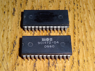
I initially read that number as 901474-04, which is the editor ROM chip from a PET 8032. But no, it's actually 901472-04. This is a ROM chip from a Commodore printer.
It may seem odd to have a printer ROM chip in there, but those chips were occasionally to be found inside PETs, normally with black paint on them to hide the number, as shown on the top chip in that photo. They were presumably bought cheap from Commodore, and were sold as security keys with the Visicalc software. It would check certain bytes in that ROM chip to see if the user had bought a licensed version of the product. This one doesn't look like it's been painted, so may have been someone cheating the system.
Same markings on the rear, but unfortunately it is not working, returning intermittent results and running a bit warm, so has been removed. With that removed, the results were the same. The display was messed up a bit, usually indication a video RAM fault, and indeed, it was showing an issue with bit 6 of the video RAM, and bit 7 of the lower bank of main RAM. That would explain why it wasn't booting.
I fitted a video RAM replacement board, which uses a modern RAM chip instead of 2114 chips, which are more difficult to get hold of. That last lot I bought about 75% were faulty.
With the video RAM replaced, the screen was clear, and I noticed another issue it had detected, reset line stuck high. I'll sort that later. At the moment, the main issue is bit 7 of the main RAM is still faulty.
With the board cleaned, I could see one track had been lifted and two pads damaged on the top, and on the bottom, half of the pads had falled off, clearly the through hole plating had come off when the original chip had been removed (apparently using a claw hammer or similar implement).
As most of the tracks are on the top side of the board, I decided to solder the chip back in, so I can make sure each pin was soldered to its track. I used a small wire to replace the missing track. The RAM chip beside it and the 74S04 were removed to give easier access to solder the chip in from the top of the board (there was nothing to solder to below).
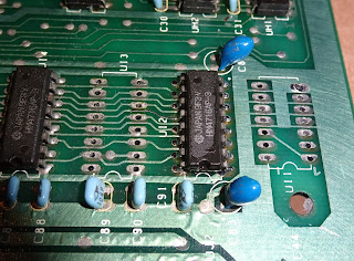
You can see there are now 8 pads are missing, a extra few were loose and not connected to anything, so they were removed. You can see the scorching to the board where the previous repairer had used too high a heat.
I actually put the chip which was originally bit 6 in the spot where the damage had been done, as that was a matching chip to the rest of the set. I didn't have an identical one, so I fitted one with similar specs where the bit 6 chip had been (in case it had to be changed later, as that would be a lot easier to remove).With those replaced, running the diagnostics again, all was well, and the PET was booting.
I ran that for a while, and a few power cycles later I noticed the keyboard wasn't working. Ah yes, the reset line was stuck high.
I confirmed this on the scope, the reset line was going high at the same time as the 5V line, so there was no low pulse which should be there to correctly initialise the chips. The reset circuit is a fairly reliable one, a 555 timer which generates a one second pulse which is then inverted and buffered. I used this same circuit on my CPU, Clock and Reset board for the RC2014.
On the PET, the 555 wasn't firing, and checking the two RC circuits, it seems the 1uF capacitor was open circuit. Ah, tantalum bead capacitors, my second least favourite capacitor (behind the RIFA brand mains filter capacitors). These have a tendency to fail, sometimes you're lucky like this one, and they fail open circuit, it is like they are not there. Other times, they fail short and go bang eventually if across a power rail. Nasty, evil blobby things, they should be banned.
Luckily, the Commodore engineers provided pads for two types of capacitors, the other being an axial ceramic capacitor (like I use on the RC2014 board), so I fitted one of those instead, and the reset pulse was present once more.
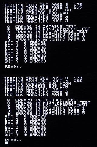
When testing these boards, I often use a BASIC memory test program. I've updated this several times, so it now tests quite a lot of things, so is quite slow, but that's often quite handy as it takes about an hour to run, so is a bit of a stability test as well.
More soak testing and several power cycles, and there is another 3032 board back up and running.


