
The new Minstrel 4D Jupiter Ace compatible kit with SD and serial loading, joystick port, posh keyboard and RC2014 slots is available to pre-order now.

https://www.thefuturewas8bit.com/minstrel4d.html
More information on the features and specifications in a previous post here:
http://blog.tynemouthsoftware.co.uk/2022/08/minstrel-4d-overview.html
We are starting to assemble all the parts that will be going into these kits. Although some of them come in disguise. Imagine my disappointment when I found out this wasn't actually a giant Toblerone.

But instead was full of chips from TFW8b stock to use in the kits.

I have already built several Minstrel 4D boards up during development. They usually start out looking quite neat

But these usually end up with one or two modifications.

Before I roll up all those changes into a new revision and everything is neat again.

But inevitably, some more changes do creep in.

Just before we opened the pre-order, I built up one final prototype version. This, I hope, will be the final version of the PCB*.
* it won't be, I've already made several changes

I have put together a few component packs

And IC packs

So it is time to put one together.
As with any kit like this, I start with the lowest height parts, and fit all the resistors, capacitors and diodes.

You lose points if you get the diodes the wrong way around (they are all marked on the board). But you get bonus points if you get all the resistor colour codes the same way around and extra bonus points if you position the capacitors so their value can be read.

I usually pop rivet TO220 packages like the MOSFET and 7805 to the board. It's not necessary, you can solder the tabs, or use a nut and bolt, or just leave them flapping about in the breeze. The MOSFET needs no additional heatsinking, it will not got warm even at full load. The 7805 does not need a heatsink for normal 4D in use. That is about 100mA, and it's not even warm. It may need a heatsink if you use a lot of expansion cards. Whatever you do, don't connect the tabs together electrically as the 7805 is 0V and the MOSFET is at 9V.
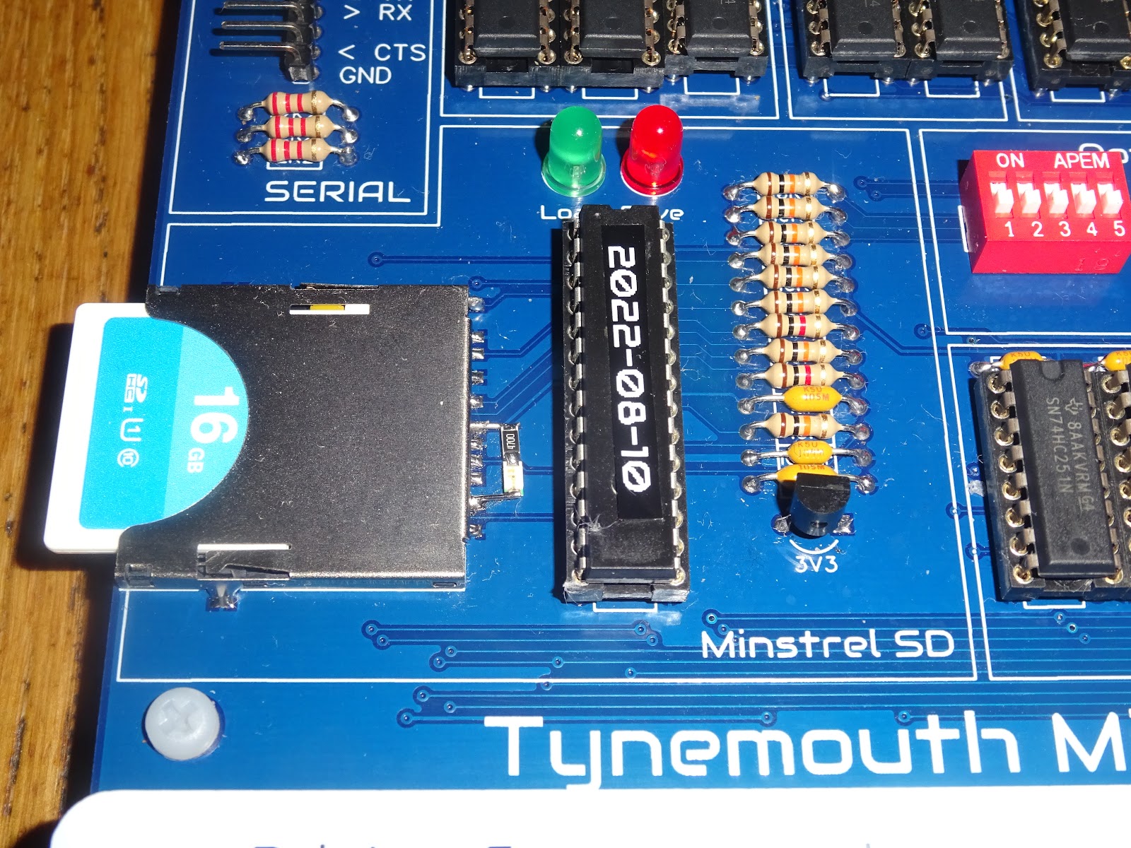
The kit will come with the SD socket presoldered, as they can be a little tricky. I guess that will be me soldering a massive pile of SD sockets then.

Just jumping ahead here, one slight change that happened in the last few days is the addition of a third LED there to show SD access. It fits in there so perfectly that I had to do it.
I was just going to flash the other LEDs, but it has been useful to see the SD access separately.
My development board has this LED added using "surface mounted" components.

For this preview build, I used an actual surface mount LED and resistor soldered directly to the socket, which although still a bodge, is a bit neater. (I did think about drilling two holes in the PCB, gluing the LED in place and wiring it on the back of the board, but there seemed a lot of opportunity to totally screw things up that way)
Back to the build, and next come the IC sockets and connectors. Points off if they are not level or the notch is the wrong way around. Here I have fitted sockets for all the ICs, so I can test batches of chips as I pack the kits. The actual kits will only come with sockets for the microcontrollers, ROM, RAM and Z80. You can fit extra sockets yourself if you like, but I think it looks better without them.

The expansion bus connectors at the side have been spaced so you can hold them in place with some pin headers inserted into the sockets to keep them vertical during soldering.

Next, it's time for the ICs. You can at this point try powering it up and see if there is 9V getting in. Then add just the 4013 and 40106 and see if the 5V will turn on and off, and is present on all the sockets etc. Then you could install the video circuitry (which is self contained and isolated) and see if you get something on the screen.

Then a few more parts, checking if the clock is running etc, until you have installed all of the chips.
Or in my case, I am fairly confident (or maybe fairly arrogant, at least fairly optimistic), so I just install them all in one go.

I have fitted the four yellow key switches for power / turbo / reset / menu, just to allow me to turn it on.
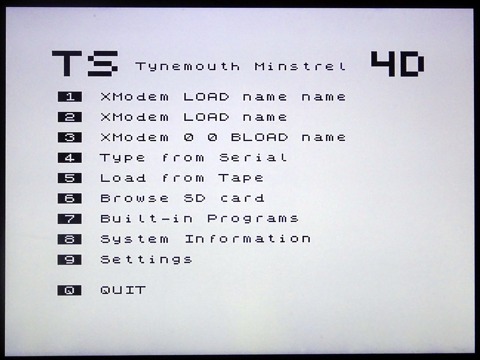
And we have a beep and a menu. Success.
Before I can try any more of that out, I need to fit the rest of the switches.

And the keyboard overlay (which is where the pictures all get a bit darker because I don't know how to tell the camera not to compensate for the white PCB)

Next it is onto cutting up lots of little squares of paper for the keys themselves.

Yay, I have a computer that runs forth and a keyboard.

There is only one thing to do, isn't there.
That all seems to be working nicely.
I had spotted a mistake on the keyboard artwork, and some of the symbols were slightly out of place, so I decided to redo them all with a new template.

The colours are just to allow me to select "all the letters" or "all the symbols" etc. Although I did add a splash of colour to the function keys.

That's all built and working nicely, ready to go?

Well, I have an advantage, I designed it. I know where the bits go.
In order to test a more representative build, a second kit was sent down to TFW8b.
There was a draft manual, but Rod did a live build on youtube relying only on the board markings (and some guy in the live chat).
If you don't have three hours to spare, here is a 60 second sped up version.
A couple of things came out of that test build, and a few changes have been made to the board, including now using three 47nF capacitors, in order to make it easier to differentiate them from the two 22pF capacitors.
Think you can do it faster or better? Well order yourself a kit and film it and send us the video.
Advertisements
The Minstrel 4D is available for preorder from The Future Was 8 bit. This will be a self assembly kit, using all through hole components. These should be shipping a 2-3 month.
https://www.thefuturewas8bit.com/minstrel4d.html
Patreon
You can support me via Patreon, and get access to advance previews of posts like this and behind the scenes updates. These are often in more detail than I can fit in here - there was a whole post on the additional 47nF capacitor with oscilloscope traces and schematics and everything.

This now also includes access to my new Patreon only Discord server for even more regular updates - I was posting pictures of this build live on there.
https://www.patreon.com/tynemouthsoftware
