
Welcome to the unexpected part 3 of this Commodore PET 2001 Repair.
In the previous posts, the board had been fixed and had reached the stage where I could load things from an SD2PET disk drive to test it properly.
All appeared to be OK until I tried out 3D Monster Maze.

Those spikes on the right hand walls should not be there. They are a glitch in the video circuit. I had seen a similar issues previously on the Minstrel 2. I think this is a similar problem, and is inherent in the design. Several chips need to change state at exactly the same time, but depending on tolerances of the timing of the chips involved, this can slip and result in a glitch.
http://blog.tynemouthsoftware.co.uk/2022/09/minstrel-2-pixel-synchronisation-part-1.html
Consider two characters next to each other. I will take the example of the right hand wall above.

The first character is a white square. The glitch appears between that and the next character which is a white and black diagonal.

I tried to take pictures of the screen, but I an not very good at that, so I have redrawn them. Separately first, and then together as they should appear on the screen.

The PET has 256 possible characters, 128 character normal characters, and a second 128 that are the same as the first 128, but inverted. To save ROM space, the inverted versions are not stored in ROM, but are generated electronically from the first 128. (on the Mini PET 40/80, since ROM space is cheap and components are not, the ROM now stores all 256 character patterns)

To generate the character output, two separate elements are required. Bit 0-6 of the character code are used to look up the character bitmap, and bit 7 controls if the character should be inverted.

In the example above, the first character is actually a black square, but the invert signal is high, so it is inverted to become the white square. The invert signal is then low for the second character which does not need to be inverted.

In an ideal world, that is what you get, however, when the logic gates involved are getting on for 45 years old, the timing can slip a little, and the invert signal might change before the character data, or vice versa. If that happens, then you can get a glitch appearing between the two characters.

The end of the black square is still being displayed, but for a fraction of a pixel, it is no longer being inverted, so you get to see a thin black line before the diagonal character starts.
This only happens in one particular circumstance, when an inverted character is next to a non-inverted one, and their edge pixels are different. If that triangle had been a circle, then you would not have noticed the black line as the circles has black columns either side of the white pixels in the middle.

The walls in 3D Monster Maze are always a good test, but you see it in other places, such as some of the space invaders ships and Rex's teeth.

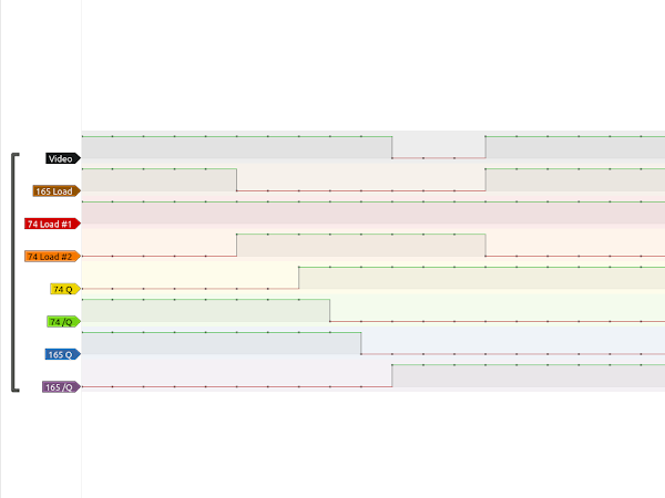
I tried to capture this on the logic analyser, but it is quite tricky as the glitch was only 5nS wide, the sampling width at the 200 MHz limit of my logic analyser (let's not mention the time I wasted with another analyser that should have been able to do 450 MHz but decided to stop working)

You can just see the /Q output of the 74LS74 changes 5nS before the Q output, and the two outputs of the 74LS165. (the glitch is a few nS later as it goes through some extra gates to combine all the signals)

However, it is not consistently that, once glitch I captured had a staircase of changes over a 15nS period.
In the the previous part of the repair, I had noticed a 74LS107 chip had been replaced by a 74HC107, which was not correct for the circuit, so I had replaced it with the originally specified part.

I wondered if maybe this being a new part, might have tighter timing, and could be causing the issue, so I reinstated the old 74HC107 to see if that made a difference.

Ah, OK, yes, it does make a difference. The spikes are now on both the left hand and right hand wall. I went back to the 74LS107 and the left hand spikes disappeared, but as before the ones on the right are still there.
There are many parts involved in the video signal generation. A 74LS74 flipflop controls the invert signal, and a 74LS165 generates the video data. It is possible that replacing one or other of those would fix the problem. It could also be down to the latch signals those chips receive, so that is several different 74LS107 chips. Or it could be the 74LS00 and 74LS08 that merge all the signals together. Most likely it will be a combination of all these.

With the Minstrel 2, I concluded that the spikes would not have been visible on a 1980s TV, so I decided I should fix them.
http://blog.tynemouthsoftware.co.uk/2022/09/minstrel-2-pixel-synchronisation-part-2.html
In this case, the reverse was true. This board was going back into a PET 2001 case, so if the glitches were not visible on the 9" CRT, then I didn't need to fix them. But, it turns out there were visible. I spoke to the owner and they said they had seen the spikes on the walls, and thought they were meant to be there.
I didn't want to start replacing all of those parts, to try to chase the problem all over the board. So I decided to look at another option.
On the 12" PETs, they had added an extra circuit to the video output, a pixel synchronisation flip flop.

I used similar circuits on the Minstrel and Mini PET kits. The video output of the Mini PET is shown here, is it is a bit clearer what is going on.

This samples the video signal once every clock cycle and outputs that version. The output of this circuit cannot have any glitches*, and will only ever by perfectly square pixels, and any glitches will be removed. (* well, unless the flip flop is faulty)

All I would need to do is interrupt the video signal after it had been merged, and insert a flip flop. I would also need to tap the 8 MHz dot clock to clock the flip flop.
Rather serendipitously, both signals are on the same chip and that chip has already been socketed and replaced. Well, I have to give this a go, haven't I.

The person who drew the PET 2001 schematics seems to have had a bit of a problem with this 74LS08 AND gate at position E2. The four gates are all drawn differently.

The first one is almost the logical equivalent, an OR gate with inverted inputs, but the output should also be inverted. The second is drawn as a NAND gate. The third and forth are correct, although to me it looks like the forth one has been tippexed out and redrawn correctly.
Anyway, I had found the two signals I was interested in. The 8MHz clock was on E2 pin 6.

And the video output was E2 pin 3.

I needed to insert the flip flop between pin 3 of the AND gate and pin 3 on the socket. (may as well keep with the hand drawn style of schematic)

To do this, I employed the "bodge another chip on top of an existing one" approach I normally reserve for my development boards.

The original pin 3 was folded upwards and connected to the flip flop input. The flip flop output is wired to a loose pin protected by a bit of shrink wrap. Ugly, but it should do the job.

It is sort of hidden by the PET ROM/RAM board. I added an extra socket to the stack to raise it up to clear the bodge chip.

All looked OK, it worked. (I didn't notice until I came to edit these pictures, but there is a shadow to the left of the first row of characters. Seems to be an echo of the last column of pixels of the next character?)

Had I fixed the problem with the spikes?

No.
It appears I had made things worse. The glitches had been amplified and were now an entire pixel wide.
Also notice the glitch on the bottom left wall is now amplified to the point of being visible.
It seems the point at which I was sampling the video signal was right on the character change, just where the glitch occurs.

OK, how can I delay that?
Well, sampling on the 74LS74 occurs on the rising edge of the clock pulse. If I could sample on the falling edge of the clock, that would be in the middle of the pixel, and should miss any glitches.
Ideally, I would change to a negative edge triggered flip flop, but I have not been able to find anything suitable.
Plan B was to invert the clock signal, so it would sample in the middle of the pixel, when it should be stable.
If it had been a slower signal, I would probably have used a transistor to make an inverter, but since this was the 8MHz clock, I decided to use a proper inverter. I didn't want to extend the bodge tower any further by adding a full size 74LS04. Nor did I want to redo all the work I had already done, so I went for plan C and use a single gate surface mount inverter, something like a 74HCT1G04.

Well, turns out I didn't have any 74HCT1G04, so plan D was a 74HCT1G02, a single NOR gate.
Those of a nervous disposition, look away now.

Some days I walk the fine line between insanity and genius, and I am never quite sure which side of the line I fall.

Factory.
Has that fixed it this time?

Yes, indeed it has.

That's better, Bang! and the glitch is gone.

I have tested various places I had seen the problem before, and everything is fine now (and I have checked and the shadow to the left has gone, that only appeared with the non-inverted flip flop version)

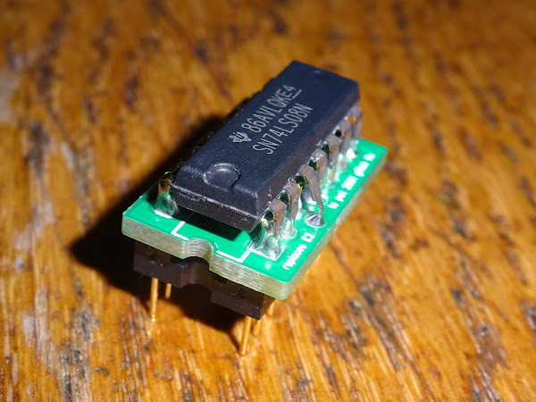
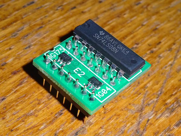
Now I know that works, I think I will make a neater PCB version. I was going to use a surface mount 74LS08, but I couldn't make it fit, so I just used a full size one.

The 74LS08 is there as before, now with surface mount inverter and flip flop. The pins underneath will fit either a turned pin or a standard dual wipe IC socket.

There should be no conflicts as the chip part overhangs some resistors on the board.

If you still have working ROM and RAM, it doesn't stand out much next to the 6502.

But most likely you will be using a PET ROM/RAM board, which just about hides the board.

As before, there is an extra 40 pin socket added below the PET ROM/RAM board to allow it to clear the new board.

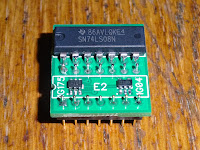
I initially designed a smaller version.
One where the socket pins were soldered direct to the IC, with only the video output on pin 3 being separated. This one had the chips underneath.

But I didn't like that design, so I will go with the larger board.

Reminds me of an old sketch....
 |
"I look up to them because they have proper circuit boards." |
 |
"I look down on him, because he is a temporary bodge, but I look up to him because he doesn't hide his SOT23's away." |
 |
"I look down on them because I am going into production." |
|
"I know my place." |
Yes, as the board played by John Cleese said, it is going into production. I have listed the PET 2001 glitch fix board on SellMyRetro. Desoldering and IC sockets required. Not suitable for 2001N or later.
The same problem exists on the 2001N, but I have looked and unfortunately the two signals are not on the same chip, so I don't think there is a similarly elegant solution for the 2001N, it is going to involve two boards, or one board and a clip onto another chip.
With the new glitch fix board fitted, I repeated all the testing, including testing the userport with a PET userport joystick.

3D Monster Maze is one of the games that support that, so time for more testing.

The spikes are gone, but I can't do anything about Rex, I'm afraid he's not going away.

Advertisements
PET 2001 Video Glitch Fix
If you have this same problem on a PET 2001 (not 2001N or later), then I have listed the boards on SellMyRetro:
PET Dual Userport Joystick
I have recently revived the PET dual userport joystick, as a through hole version, available from my SellMyRetro store:
- Assembled - https://www.sellmyretro.com/offer/details/64260
- Full Kit - https://www.sellmyretro.com/offer/details/64257
- PCB Only - https://www.sellmyretro.com/offer/details/64256

Minstrels and Mini PETs
Minstrel and Mini PET kits and ready built units are available from my SellMyRetro store.

Patreon
You can support me via Patreon, and get access to advance previews of posts like this and behind the scenes updates. These are often in more detail than I can fit in here, and some of these posts contain bits from several Patreon posts. This also includes access to my Patreon only Discord server for even more regular updates.
