Sunday, 23 February 2025

A New Penultimate Cartridge Help Page

The VIC20 Penultimate Cartridge currently has a built in help page, press H and it appears.

It covers some of the main shortcut keys, but I would ideally have added at least another page to cover all the options and give some more information.

The trouble is the cartridge is packed full of things, so much so that I am always running out of space.

That has happened again. I am currently working on adding a new feature to the cartridge, and so for testing, I have been producing versions with the games list removed. That is not needed during the testing, and frees up the space required in order to test the new feature.

You might have noticed that on some recent videos from TFW8b.

I got to thinking, could I solve both problems in one go?

If I extracted the help into a separate program, that would free up space in the cartridge and would also allow me to expand the help.

Perfect.

Should be easy, 5 minute job ....

.... 5 days later .....

Let me go back to the start.

Writing this in BASIC might have been an easier option, but that would probably produce a larger file size which ran slower.

Using anything other than BASIC to write to the screen on a Commodore machine can be a world of pain, as the character code don't match what appears in the video RAM, and the compilers and assemblers attempt to address this in ways that generally make it worse and you get into trying to work out if you should add or remove $40 or $80 or $C0 or some other random number, to each character.

See all the fun I had with cheese and chive on the PET

I decided to try and start with some already working code. 

I had successfully used a few different approaches in the past.

VIC20 Dead Test +

Going back many many years to the VIC20 Dead Test, that had a screen full of text, and was written in assembler.

Here I built up the screen programmatically, using macros to clean up the code.

That took quite a bit of code, drawing the lines for the boxes and adding all the text string.

Penultimate Cartridge Self Test

When I came to do something similar again, I got to thinking it would be easier to just have a pre-formatted screen full of text and just copy it into screen RAM in one go.

That is exactly what I did.

I built up a block of characters in the assembly file, and set it to be based at $1E00, the location of the screen RAM, so it gets loaded into the screen RAM as the program was loaded.

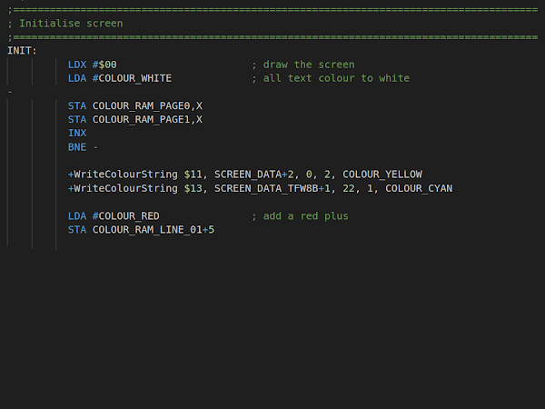
All I needed to do then was set all the colour RAM to have white text and add the few bits of fixed colour text were manually changed.

Help Text

That seemed the best option to use for the help text, I needed multiple pages, so I couldn't use the code loaded direct to screen RAM trick, but I could still pre-format several help pages and copy them into screen RAM as required.

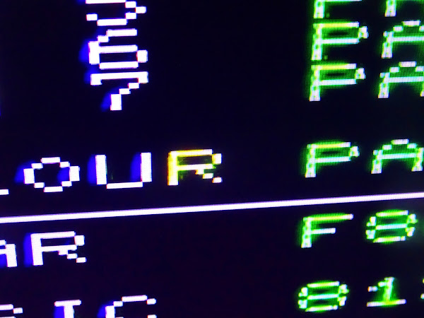
You can see the remnants of the self test screen there in the first go at the help page.

You can also see where the problem starts.

Uppercase inverse text didn't work, I get a double quote instead of a capital M. The rounded corners also did not work, and I got uppercase J and K instead.

But it seemed like it was still the best option, so I set to work fixing those.

That required some user defined graphics. This is where it also gets tricky.

VIC chip addressing

The VIC chip accesses three areas of memory.

  • Screen RAM says the first character is 'A'
  • Colour RAM says the first character is green
  • Character RAM contains the bitmap pattern to produce the 'A'

The colour RAM is fixed, in one of two locations, $9400 or $9600 (for reasons which are unlikely to become clear again at the moment).

The other two can be moved around within the VIC address space. It is important to note that this is arranged differently to the CPU address space.

Borrowing that table from one of the Mini VIC posts, you can see the VIC can access various areas of the internal bits of the VIC20, but nothing in the cartridge port.

The mapping of the different areas is configured using register $9005 (and a bit of $9002).

This is in two halves.

  • Bits 0-3 set the location of the character RAM
  • Bits 4-7 set the location of the screen RAM

By changing those values, you can move the screen and character locations around.

Here is a table of useful values

  • $Cx - Video RAM at $1000
  • $Dx - Video RAM at $1400
  • $Ex - Video RAM at $1800
  • $Fx - Video RAM at $1C00
  • $x0 - Character ROM $8000
  • $x1 - Character ROM $8400
  • $x2 - Character ROM $8800
  • $x3 - Character ROM $8C00

There is also one more thing, bit 7 of $9002. If this is high, then add $0200 to the Video RAM address (i.e. Cx = $1200 etc.)

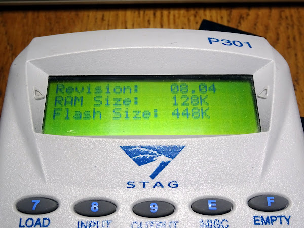
The default value of $9005 is $F0, and $9002 is $96, so video RAM starts at $1E00 ($1C00 + $0200) and character ROM starts at $8000.

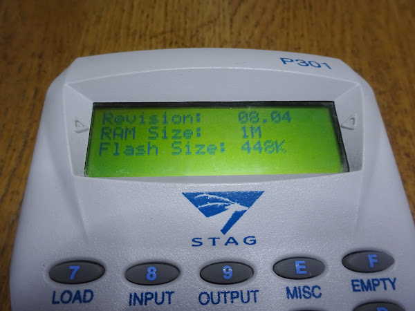
With 8K or more RAM installed, the values change to $C0 and $16, so video RAM now starts at $1000 ($1000 + $0000).

There is also nothing to stop you setting the character ROM as screen RAM or setting them both to the same location or lots of other things that will not work etc.

You can also do odd things like setting the video RAM to $0000 with $9005 = $80, which gives you a visualisation of the first 506 bytes of RAM including zero page and the stack.


Character RAM base address

-
-
$9005 bit 7
$9005 bit 6
$9005 bit 5
$9005 bit 4
-
-
VIC
CPU
A15
A14
A13
A12
A11
A10
A9
A8
Base
Base
0
0
0
0
0
0
0
0
$0000
$8000
0
0
0
0
0
1
0
0
$0400
$8400
0
0
0
0
1
0
0
0
$0800
$8800
0
0
0
0
1
1
0
0
$0C00
$8C00
0
0
1
1
0
0
0
0
$3000
$1000
0
0
1
1
0
1
0
0
$3400
$1400
0
0
1
1
1
0
0
0
$3800
$1800
0
0
1
1
1
1
0
0
$3C00
$1C00

The character memory

This default setup gets all the characters from ROM. Which is fine if you want the standard PETSCII characters, but if you want to define your own, you have to move the start of the character memory into an area of RAM.

To create your own characters, add these to the mix

  • $xC - Character memory at $1000
  • $xD - Character memory at $1400
  • $xE - Character memory at $1800
  • $xF - Character memory at $1C00

The VIC20 character ROM is made up of 8 bytes per character, and so 256 characters takes up 2K. That is a big chunk of available RAM to dedicate to graphics on an unexpanded VIC, but when you have 35K or more to add, it is acceptable.

Screen RAM is a lower requirement, 23 rows of 22 characters, and 1 byte per character, which is 506 bytes.

If you set $900F to $CE, you would have the video RAM at $1000-$11FA, and the character RAM from $1800-$1FFF.

One trick you can use is $CF, set the character memory to start at $1C00. It is 2K long, $0800 bytes, so you might think it would run from $1C00-$23FF. But $2000 upwards is expansion RAM in the cartridge slot, and the VIC cannot access that. What actually happens is the VIC address wraps around and you actually get $1C00-$1FFF for the first 128 characters, and then the second 128 characters come from the character ROM at $8000-$13FF.

Look again at the memory map and it should be easier to see how address wraps around.

It turned out the characters that I needed were not in the section of the character ROM that was visible, so I went for the full 2K option to be able to get all the characters I needed, including the rounded corners and inverse upper and lower case letters.

I was able to start refining things such as making the dash smaller so I didn't need the spaces either side of it.

To match the main menu, I extended the side bars to the edge, so I needed custom rounded bottom corners.

I tried making the navigation buttons big and yellow. Not sure how I feel about those.

Well, now I am here, maybe I could use the logo from the cartridge menu. I wasn't sure if I could make it work, but I tried the first few characters and it looked promising.

It's going to need two lines.

Looks good.

I just need to make the 3 yellow to match.

I also made the navigation buttons smaller, that looks better.

Next came the task of arranging all the text I needed into several pages.

It worked out best as three pages.

I have had to censor a section of page 3 covering the new feature. My Patreon supporters will find out about that in a few days time, if you are not on there, look out for an official announcement from TFW8b #soon.

All that was left was adding that to the Utilities menu.

Sorted.

Now there is more detailed help, and enough space in the menu ROM to add the new functionality. More on that very soon.


Advertisements

The patched versions of Bandits and Multitron are included in the new Penultimate +3 version which also has a built in SD2IEC drive.

Shipping now with the new feature, more on that next week.


Tindie

Minstrel 2 and 3 kits are available from my Tindie store, with worldwide shipping. Versions avaiable for ZX81 case or standalone with keyboard, and also Misntrel 3 with ZXpand microSD card interface (andn now available as PCB only).

I will slowly be moving things over there from my SellMyRetro store, so if there is anything that you want, let me know and I'll add it.

Patreon

You can support me via Patreon, and get access to advance previews of posts like this and behind the scenes updates. This particular post had a section removed on the way the bits add up to make the was originally about twice as long before I cut it down, so if you want all that detail, join the Patreon. This also includes access to my Patreon only Discord server for even more regular updates.

Sunday, 16 February 2025

Stag P301 EPROM programmer P322 memory upgrade

Way back in 2018, a wrote a post the Stag P301 EPROM programmer.

It is quite a neat all in one EPROM programmer that can be used stand alone or connected to a PC via a serial port.

It is good at dealing with some of the older more esoteric types of EPROM that the modern USB programmers can't touch.

Battery Upgrade Upgrade

In that post, I replaced the dead 8.4V Ni-Cd battery pack with some AAA battery holders and some Ni-MH cells. I originally used 7 cells to match the nominal voltage of the old pack. 

The unit can also run from 12V DC, so I wondered if I could extend the battery life a little. I tested the battery gauge with a bench power supply, and the full 8 bars was reached at about 9.6V. Given that, it seemed reasonable to add another cell to make the nominal voltage up to 9.6V to match.

To test that, I tacked on a single AAA cell holder to make the pack up to 8 cells. That fitted perfectly in the space available.

I did intend to go back and tidy that up with two 4 cell holders, I am sure I ordered a set sometime in the last 7 years........

I guess I will just leave it like that, it has been working well with 8 cells.

RAM Upgrade

When I was writing that post in 2018, I had access to another unit, one that had a P322 1MB memory upgrade. The standard programmer has 128K of RAM and can only program chips up to that size (it would be useful if it could do larger chips in multiple passes).

At the time, I looked at that and it did look like it could be replicated, but I did not have the time to reverse engineer it.

There is a useful resource for owners of these programmers, by Matthieu Benoit.

I contacted Matthieu when I was writing that first post and asked if those upgrade modules were available anywhere. At the time, the answer was no.

Roll on six years, and Matthieu emailed me to let me know someone had reverse engineered the board and published the design files.

I downloaded those and added that to my list of things to do.

Roll on another six months and I finally ordered the PCBs.

The gerber files seemed fine as they were, so I just uploaded them to the PCB manufacturer.

Thanks to Zachary Goode for their redesign work.

The notes on the site suggested using two M5M5408BFP-70H RAM chips, one on the front, one on the back. That was the same part as used on the original.

I couldn't find those from my usual suppliers, so I used a pair of the more readily available (and still in production) Alliance AS6C4008-55.

I tried to find shrouded versions of the pin headers to match the original, but I couldn't find any that looked right, so I went for the pins only version specified.

The lack of the shroud around the pins means it is a little tricky to align the module in place.

I thought it would be safer to take the back off to get better access.

It was also good to confirm the main power supply was a switch mode MC34063A, and there were also a pair of UA723 regulators, so all should be fine with the battery pack upgrade.

It is easier to see now to check it is aligned correctly.

It was a little tricky getting it to fit, I soldered the connectors in the middle of the pads, it was only when I came to fit it that I remembered the guide recommended fitting them closer to the edges.

All fits nicely back in the case.

Time to give it a go.

For reference, this is what it used to say, 128K of RAM installed (1 megabit). Enough for most of the standard EPROM types, up to 27C010, but not supporting the 27C020, 040 or 080 and similar chips.

With the upgrade fitted, that now shows 1M of RAM (8 megabits).

To test this, I went straight to a 1M EPROM, a 27C080. It read that all in one go and then I wrote it out to a freshly erased 27C080.

That passed the program and verify, and I also checked it my usual USB programmer.

Excellent, that should have tested the whole 1M of RAM, with that working, it opens up more devices I can program.

I have some spare PCBs left, if anyone else still uses one of those programmers and wants a RAM upgrade. I don't think I will list these on Tindie, so use the contact link above if interested.


Adverts

There are a selection of repair and upgrade parts for various machines listed on my Tindie store, many of which can be seen on this PET 2001 board.

Be the envy of all your friends with one of the limited edition run of blue PET Diagnostics modules.

Patreon

You can support me via Patreon, and get access to advance previews of development logs on new projects and behind the scenes updates. These are often in more detail than I can fit in here, and this post contains bits from several Patreon posts. This also includes access to my Patreon only Discord server for even more regular updates.

Sunday, 9 February 2025

Mini VIC Revisited Part 5

Over the last few weeks I have been using the Mini VIC a lot for testing, and making a few minor changes along the way. Time to roll up all of those small updates. (this from Patreon November 2024)

Clocks

I identified the clock generation wasn't great in a previous post. I thought I should test out the theory, so make a clock generator that plugged into the 74HC02 socket on the Mini VIC.

I am a little worried that my bodges are getting neater.

I had already laid out the PCB, so I followed a similar arrangement.

This uses a more standard crystal oscillator approach. Two crystal oscillators in fact, so I am only switching the logic level clock signals rather than the connections to the crystal.

That works rather nicely and the system has been very stable throughout the Penultimate +3 testing.

I am pretty happy with that for "non-overlapping clocks".

I had an early NTSC VIC20 on the bench recently and took the opportunity to checked out the clocks generated on that board.

That looks a bit wobbly, but if I do the merge again, it seems clean enough (if the threshold is right).

I also captured the clock pulses on three other VIC20 boards I was using to test things on the Penultimate +3 but unfortunately I have lost all those traces.

When I get the Keysight scope that could do screenshots and save to USB, that was a game changer for showing scope traces in the blog posts. I use these a lot, so I have a script to automatically crop them to 4:3 these days.

When I looked for a USB stick to use, I found this 1GB USB stick that was otherwise not much use and thought it would be ideal. Turns out it wasn't. This USB stick has now spoiled three blog posts. It came from Keysight as part of some promo thing I guess in April 2017 based on the markings.

I lost a load of traces for the Sony cassette recorder post a few months ago, but reformatted it and it appeared to be working again. No more problems until today when it has failed again and lost most of the traces for this post and the VIC-1001 board repair post.


Power

I think the original 2 pin VIC 20 used a 9V AC power supply for convenience. That was the same way the PET had worked, AC in from a transformer and the rectification and regulation all handled on the board.

I am not 100% sure where the 7 pin DIN power supply was first used, the VIC20-CR, the Max or the C64?

Well, I say 7 pin, but many of them only had 4 pins connected. Two are 9V AC, and the rest are either 0V or 5V DC pins. All are wired in parallel on the socket, but the plugs often only have one 0V and one 5V.

It seems to suit the VIC20-CR best. The 5V DC is moved into the power supply itself, so that removes the need for the rectifier and regulator and the massive heatsink. The 9V AC is retained to be backwardly compatible with the userport of the previous model, and also used to generate an unregulated 9V DC supply for the datasette drive. It is regulated down to around 6V for that by the big TIP29 transistor near the port.

The Commodore 64 complicated things. Again the 9V AC is retained to be backwardly compatible with the userport of the previous model and for the datasette power. That unregulated 9V also provides power to a 7805 to generate a separate supply for the VIC-II and clock chip inside the tin can. But it also needs 12V. So the 9V AC feeds a voltage doubler to generate about 15V DC and then is regulated down to 12V for the VIC-II and SID.

Finally, a tap from the 9V AC is used to generate a line frequency reference, a 50Hz or 60Hz pulse that is fed to the TOD (Time of Day) input the 6526 VIA chips.

There are an awful lot of these things around. There is just one problem with them, well two.

Firstly, the 5V supply is flawed, and they quite often fail with the 5V rail rising upwards of 7V, taking out lots of the chips on the C64.

The second problem is they are potted, so you can't repair (or ideally replace) the 5V supply circuitry. Therefore, they should be avoided.

I had to hunt around to find this one for the photo. I have a box of them somewhere. I never use them. This one is showing about 5.31V on the 5V rail, so I wouldn't be happy using that.

I would be mad to design the Mini VIC to use one of those?

Well, I did, but with a very important caveat.

I do not connect to the 5V-7V DC supply at all. I ignore it and just connect to the 9V AC.

As such, it is quite a handy source of 9V AC from something which would otherwise be consigned to a box in a dark corner somewhere (or straight into e-waste).

I designed the board to accept either 9V AC or DC. The input is rectified to give 9V DC, and then regulated with a 7805 to give the 5V DC. The modern logic uses less power than the original board, so the approximately 1A rated supply will do just fine.

You can also power it form 9V DC if you prefer. There is no requirement for an AC dervied time of day signal (as on the C64), or any voltage doubler circuitry (as on the C64), or any other reason for AC on the board itself.

It is fed to the userport for use by external devices. I am not aware of any that specifically need AC. If any userport device requires AC, then feed the board AC. Otherwise, AC or DC is fine.

(and also note the caveat about 9V DC with a bridge rectifier and be aware of any ground loops or shared supplies - http://blog.tynemouthsoftware.co.uk/2024/03/why-dont-you-use-a-bridge-rectifier.html)

There are two sets of pads on the board, one for a 2.1mm DC power jack, as used on all my other kits, as well as one for the 7 pin DIN socket.

Testing

I didn't want to go directly to a C64 power supply, as I wanted to be able to monitor the current during testing, but I wanted to use the 7 pin DIN as that looked better for photos of the board.

I ended up making a 9V DC barrel jack to 7 pin DIN adapter so I could test both versions.

(actually, I made two. The first one I lost and I couldn't find it, so made a better one for these photos. I then almost immediately found the first one. It's been one of those weeks and it's only Monday)

(edit, as I come to post this, I have now lost both of those adapters)

However, the first time I tried it, it didn't work, totally dead. When I checked over, I found the fuse had blown. Not ideal.

I was impatient, so I tried clipping directly to the power switch pins and it worked fine, so I have just been using that throughout the testing.

Once I had finished testing, I had a look at fixing that.

I assumed I must have messed up the layout somehow to cause a short, or there was a solder bridge somewhere. I couldn't spot anything in the design that was wrong, so I took the board out of the VIC20 case and investigated further.

Well, there's ya problem.

Looks like I put the fuse holder too close to the edge of the board. I was trying to keep it away from the metalwork of the cartridge shield, and inadvertently moved it too close to the sideplate.

For the next revision, I have shuffled things around to move the fuse a bit lower, away from all the metalwork.

As a temporary fix, I desoldered that end of the fuse and cut the leg off. I soldered it to the trace on the top of the board and put a bit of tape over the bottom side.

One new fuse later and away we go.

The DC jack is connected to my bench supply so I can monitor the current use and try different voltages to check the limits.

The Mini VIC alone with a vintage VIC chip and MOS 6502 uses about 500mA. Add a Penultimate +3, and that rises to about 750mA. Still within the limits of the 1A supply.

If you need more power for accessories, use a more powerful supply.

I am impressed with how well the 7805 is going just rived to the board with no heatsink just a bit of tinned copper trace on the PCB. It gets warm, but no where near as hot as say the VIC chip.

I have had that running pretty much all day for several days when testing the Penultimate +3. (there are 250+ games on the menu, plus utilities, programming tools, file browser and different memory options, all of which have to be tested).

I will probably suggest a switching regulator for the final version, depends how things work out. Switching to a W65C02S should reduce that a bit. And VIC chip replacement current consumption is yet to be seen.

I did try it with the AC supply again, and it sort of works, but it seems a messed up with the reservoir capacitor. It was meant to be 2200uF, but somehow ended up as 220uF. With an extra capacitor clipped on, it worked fine.


Two problems remain.

  1. The chrominance signal is not very good.
  2. There occasional corruptions to the colour RAM only noticed during the Dead Test or similar soak testing.

(I don't have any of the video signal captures, I am going to have to do all those again, but not today. Frustratingly I have lost the before and after for the mods I did, so I will keep this bit short.)

Here you can see both problems. The R of colour has been corrupted and gone yellow.

This shows why composite video is never going to be as clear as RGB. Composite is just what it says, a composite of a sharp black and white image with some colour information overlaid on top of it.

And yes, I still need to fix the chroma timing on PAL.


Adverts

The Mini VIC kits are not available yet, but there are still Minstrel 2 and Minstrel 3 kits available.

I have also turned back on EU shipping, with a caveat that there will be extra delays and charges at customs, sorry, nothing I can do about that.

You can now get a Minstrel 2 kit for $200. 1980s pricing.

Or you can get a Minstrel 3 kit for $200

Patreon

You can support me via Patreon, and get access to advance previews of development logs on new projects and behind the scenes updates. These are often in more detail than I can fit in here, and this post contains bits from several Patreon posts. This also includes access to my Patreon only Discord server for even more regular updates.