
This is a combination of a several Patreon posts from November 2024, the ongoing development of the Mini VIC clock circuitry.
When I designed the first version of the Mini VIC back in 2020 (the green board), I deviated quite a lot from the standard VIC20 design. Some of the changes were justified, but there was also a bit of "well I can do better than that" style arrogance.
It ended up being a bit of a flawed design, I over-complicated the ROM section trying to use a single ROM chip for character, BASIC and KERNAL ROMs, and over-complicated the RAM section trying to have all the RAM options when it is easier to just have the standard 5K and leave the rest to whatever you plug into the cartridge port (let's face it, it'll be a Penultimate Cartridge, won't it)

When I revisited that project (the new yellow board), I decided to go back to something a lot closer to the VIC20 design, picking and choosing from the best versions from various iterations of the design, the VIC-1001 the VIC20 2 pin and the CR versions.

One part of the design that I reversed was the clock circuit. I thought I should try to follow the original.

And the results were awful.
I have seen better clock signals coming out of a ZX Spectrum.

I am not sure if it is my implementation, the crystal traces ended up a bit longer than I would have liked. Maybe it is not suited to 74HC series logic over the 7402 or 74S02 originally used.
Either way, it has to go.
Back to the old green board
On the previous version of the Mini VIC, I had used a more familiar oscillator configuration with an XOR gate, and then used two more XOR gates to generate inverted and non inverted outputs. It should be the same latency though both gates, so should give perfect complimentary outputs.

I wondered if that was any better that the NOR gate version, so I fired the old board up. And yes, the output is much nicer.

The clocks were a lot cleaner.

My scope was playing up at that point, both clocks were as clean as the top one.
Regardless, the clocks were cleaner again, so I tried running the new yellow board from those.

It looked better, and ran for a while with no issues.

But there was still the occasional glitch in the colour RAM after testing.

I have yet to get to the bottom of the issue, but it is odd that it mostly affects the left of (rather ironically) the colour RAM line and the URL at the bottom of the screen (neither of which are on a page border or anything like that unfortunately
Back to the Schematics
There have been quite a few versions of the clock circuit.
According to the datasheet for the 6560, the idea is to provide two non-overlapping clock phases.

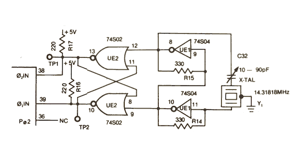
The oldest design is the VIC-1001. That had an inverter based oscillator, then a NOR gate flip flop, which should ensure the two outputs are non-overlapping.
The two pin VIC PAL model kept the NOR flip flop, and used the other two NOR gates on the same chip as the oscillator. They also added a 74LS74 flip flop to drop the 8.86 MHz clock down to 4.43MHz for the PAL VIC chip. (it only halves the one signal, the other would have still been 8.86 MHz, odd since they could have had two complimentary 4.43MHz clocks from the Q and /Q outputs of the flip flop?)

The NTSC VIC20 model also used a NOR gate oscillator, but rather than the flip flop, it just buffered (and in passing inverted) the two signals.

The CR VIC20s continued with the NOR gate buffers, but the PAL version got a 4.43MHz crystal, so it didn't need the 74LS74 any more. Now both inputs are 4.43MHz, the 6561 VIC chips seems happy either way.
For the revisited Mini VIC, I had gone with the CR version with four NOR gates, and added jumpers to select the two crystals.

After seeing how bad that was, I rejigged that as a bit of a hybrid of all of the above.

I have kept the NOR gate oscillator, but reconfigured the other two NOR gates as a flip flop.

That seems to give a slightly cleaner signal.

The 1.108MHz CPU clock is divided down from the 4.43MHz signal, and that is looking good, nice and clean after having been buffered by a NAND gate.
(if you want to know more about that side of things, see an old post on VIC20 clocks)
Did the clock mods help? No.
Diversion, Penultimate +3
I left that for a while because it was basically working, and turned out to be very useful when testing the Penultimate +3 Cartridge.

Available now from The Future Was 8 bit (yes, I know the URL says "plus two")
Revisited Clock Revisited
After the testing was complete. I wanted to have another look at the clock options.
I decided to go back to the oscillator circuit I normally use. That seems pretty reliable. I started with a 74HC00, and used one of the two spare gates to add an extra inverter (not shown) to generate a complimentary output.

I built that up on a small breadboard for ease of testing.

This is equivalent to the circuit used in the VIC20 CR, although that had an additional gate buffering each of those signals with an extra pullup, just due to the limited drive capabilities of those chips.

Those are much nicer clock pulse. None of the harmonics I was getting on the HC02 circuit
The problem is that it does fail the requirement for a "Non Overlapping Two Phase Clock".

The top trace goes high before the bottom one has gone low, due to the uneven propagation delay. The second signal is going through one extra gate to invert it, so it is delayed by 5-10ns, which isn't much until you consider the pulse is only 112ns.

At the end of the pulse you also get a period where no clock would register as high for about 20ns. That probably isn't a problem, may even be desirable, but the overlap at the start is still there.
Ideas started jumping around my head about delaying pulses by a gate or two, then ANDing them with the non-delayed version to get a clear pulse and a clear gap, but that looks like it would need most of a 74HC04 and a 74HC08 to implement it..
Time to look back to the original designs and the flip flop circuit used on the VIC-1001 and some of the 2 pins.

I turned the output into a flip flop using the other spare gate on the 74HC00.

I was disappointed to see that although it worked, the signal appeared quite asymmetric.

One clock signal was about 100ns, the other about 125ns (instead of the ideal 112ns). Maybe that is why they abandoned that in favour of just buffering the signal on later VICs?
Since that was also potentially caused by the difference in propagation delay, I decided to go back to my design from the previous (green) board.

Here I use the same type of oscillator circuit. This time using a 74HC86 so that I could use two extra gates to buffer the signal, one inverting, one not, to give the two phases of the clock with identical propagation delays.

The breadboard was revised again.

Well, that looks pretty good to me.

Perfectly synchronised complimentary clock pulses. Still slightly asymmetric, but not as bad as the flip flop.
Time to update the design for the next revision of the Mini VIC.
One the first board (the green one), I had used jumpers to select the crystal.

I am not sure that is ideal, so since I have a spare XOR gate, I think I will wire up both oscillators and select which of those clock signals is feed to the complimentary output buffers.

I don't think the noise from the two oscillators should be a problem. We will see. If you only ever plan to fit one type of VIC chip, you could only populate the parts for the oscillator you need and hard wire the jumper link. (I think I could possibly put a jumper to ground on pin 1 or pin 4 to disable the other oscillator if it turns out to be necessary?)
Further testing with the breadboarded 74HC86 based clock circuit seems to be working nicely.

I have been using the Penultimate tester as a soak test.

I am still seeing issues with colour RAM corruption in Dead Test, but I haven't noticed anything whilst testing any of the games. Again, it is affecting the same sort of place, this time the L of the world COLOUR has been corrupted. It passed the actual test, but somehow got corrupted when it was restored after the test.
The various internal timing clocks and write pulses is something I plan to investigate, and again I thought that was best going back to the original design (in this case, the last version the VIC20-CR).

I need to get the logic analyser out and have a good look at what is going on with this lot and see if I can actually do a better job.

And yes, I still need to fix the chroma timing on PAL.
Adverts
The Mini VIC kits are not available yet, but there are still Minstrel 2 and Minstrel 3 kits available.
You can now get a Minstrel 2 kit for $200. 1980s pricing.

Or you can get a Minstrel 3 kit for $200

Patreon
You can support me via Patreon, and get access to advance previews of development logs on new projects and behind the scenes updates. These are often in more detail than I can fit in here, and this post contains bits from several Patreon posts. This also includes access to my Patreon only Discord server for even more regular updates.
