Monday 31 October 2016

Spanish Spectrum+ 128K 'Toastrack'

This is an old post, preserved for reference.
The products and services mentioned within are no longer available.

This is the Spanish version of the Sinclair Spectrum+ 128K.
Based on the Spectrum+ 48K it gets the nickname Toastrack from the large finned heatsink on the right hand side.
This particular one doesn't actually have the heatsink when it arrived, Here is the UK version for comparison.
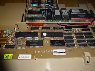
Inside, the 7805 voltage regulator is still there and would have been bolted to the heatsink (here I've borrowed one from the UK model). The board is larger than the original Spectrum+ 48K, which used the same board as the original Spectrum 48K.
It does share the same keyboard layout and keyboard membrane as the Spectrum+ 48K, and the same awful power supply circuits from the Spectrum. This takes 9V DC in and uses the 7805 to generate 5V (and lots of heat), and a switching circuit that generates two 12V rails (one from the RAM, one for the video) and -5V for the RAM. This was revised with every release of the original Spectrum and was always prone to failure, with often caused the 4116 RAM chips to fail.
Most of the chips are soldered in, but the ROM is socketed, and rather than a mask ROM, this is a 27256 EPROM with a handwritten 'DERBY' label (that was the codename of this model). Not sure if that is 'SP' for 'Spanish' below?
This is PCB version 2-1, I think there was a version 2 before this. The UK versions are 6K and 6U. All the chips along the bottom of the board are D4164C chips, providing the 128K of RAM to the Spectrum. All arranged as two chunks of 64K, rather than the contended 16K and upper 32K in the 48K model.
The large chip in the centre is the ULA, the 48 pin version used on this model and the original grey coloured Spectrum +2. This is now the correct way around. When it arrived, it was the wrong way around. Not sure when that happened, I hope it was never powered up like that. Note R127 and R128 just below the ULA are missing, in fact the were fitted and cut off from above, the tails are still present.
New with this model was an RGB output connector, as well as RF output. This is the same connector as used on later models, the levels are the same as the grey +2, and thus not compatible with the black +2A/+2B/+3 models.
There is a new sound chips, an AY-3-8912A, but no internal speaker this time, and the Mic and Ear connectors were moved to the side.
Next to them is an RS232 port. This does have proper 1488/1489 buffers, so runs at proper RS232 levels (unlike the port on the interface 1). There is no UART, so the serial interface provided by bit toggling on the AY-3-8912A, so the speed is limited as there is no hardware buffering. It uses a variation of the BT telephone jack, also used on the +2 range and the QL. It has a different key, so normal BT connectors cannot be used. I understand there was a late version of this with a 9 way D connector, but that was far too standard to be kept and was dropped again for the +2 which had the BT connectors again.
Although largely compatible with the original Spectrum, there were a few issues which stopped various add ons working. Most notably the omission of the clock signal form the edge connector. The pin which used to be clock is not connected at all, which will cause problems for anything more complicated than a joystick port.
I've been doing a lot of work with Spectrum's recently, and the clock signal is a real problem throughout the range. Here they had the decency to leave it unconnected. On the UK Spectrum+128K, they did connect it, but it is such a low level it is barely usable. (the dotted green line is 5V, the yellow clock line is less that 2V peak to peak). There is a long blog post on the way detailing all the fun involved in trying to get a decent clock signal from all the machines in the Spectrum range. Look out for lots more of these 'scope pics coming soon.
The UK version of the Spectrum+ 128K followed a year later, once they had sold all of the stockpile of Spectrum+ 48K machines. The UK model (at the top of the picture) was essentially the same machine. The one in the photo is a late version, by that point Amstrad were producing the ULA chips rather than Ferranti. I admit to being surprised to see the Amstrad logo in a Toastrack, but the date code (early 1986) matches the rest of the chips on the board.
Externally they were pretty similar. the Spanish keyboard was the same as the Spanish Spectrum+ 48K had been. I do like the true and inverse video symbols, and 'MODO EXTENDIDO' just sounds better. They UK version had a bit of a red theme, with red plastic springs on the keyboard stand, a red Sinclair logo and a red 128K.
I haven't mentioned one of the unique things about the Spanish Spectrum+ 128K, It came with something that plugged into another BT jack on the front of the keyboard, labelled 'KEYPAD'. More on that next time. [Update: Keypad article]
Oh yes, I should also add the Spectrum doesn't work, but we'll sort that next time.

Wednesday 19 October 2016

ICL One Per Desk Microdrive Repair

This is an old post, preserved for reference.
The products and services mentioned within are no longer available.

The previous blog post on the repair of a BT Merlin Tonto (ICL One Per Desk) covered the cleanup and monitor / power supply.
Once it was up and running, it was clear that neither of the two microdrives were working. When attempting to access either drive there was no response, no motor noise, no activity lights.
The microdrive was a cassette tape loop based storage device, with 5m of 1.9mm tape spooled in a small cartridge, like an 8 track cartridge. I don't know why I think that will help, if you don't know what a microdrive is, you probably don't know what an 8 track cartridge is either.
There is no spool, the tape is pulled around in a big loop by a capstan from the side, the tape head sticks in from the top. Those foam pads tend to wear out, so need to be replaced to keep the tape pressed against the head.
These were introduced for the ZX Spectrum, as a replacement for standard audio cassette storage and a much cheaper alternative to disk based solutions. You could chain up to 8 of these drives together to provide massive storage capability for the Spectrum. (or why not just buy 8 cartridges and swap them over in the one drive?)
It may look like the microdrive just plugs into the side of the Spectrum, but there is in fact a larger interface unit the 'Interface 1' which the Spectrum is sitting on.This contains the drive circuits and ROM patches for the additional commands necessary to use Microdrive storage.
This provided the Spectrum with 'up to' 100K per cartridge, although in reality this was a lot less. As the cartridges aged, the tape would stretch, so you could format it again and the capacity would increase slightly (probably in proportion to a decrease in reliability).
The microdrives were again used in the Sinclair QL, with two of them intregrated into the QLs case and intended as the QLs main storage device. The BT Merlin Tonto was based on parts of the QL and included two microdrives as well.
One of the articles I have read say that ICL re-engineered these microdrives to be better than the Sinclair versions, I'm not sure about that. Here is a Spectrum microdrive.
Theses are the QL ones.
And these are the ICL ones.
The plastic chassis looks identical, same motors, same switches,  the PCB was laid out differently, but basically the same. Comparing one of those to the Spectrum one, I can't see much difference. Sinclair on the left, ICL on the right.
On the rear, again I'm struggling to see any mayor mechanical differences.
The main electronic part on these is, true to form for Sinclair, a Ferranti ULA, here in the Sincalir microdrive. You can see the two edge connectors on the rear PCB, one on each side.
These are chained in series. Most of the pins pass through from one microdrive to another. The exception is the data signal. This goes into the first device, is processed and then passed onto the next device. Presumably removing anything addressed to it, and passing on the rest.
The same part 2G007E is used on the ICL version, and like the Sinclair versions they are chained in series. When I checked, there was data going into the first chip, but it was doing nothing with it. It was also not passing on any data to the second drive, so it looks like a faulty ULA.
This could mean the second drive is actually fine, and just wasn't getting the data passed to it from the first drive. To test this, I rewired the connectors so the first drive was disconnected, and the second was connected to the main board.
Success, that drive was fine, One cartridge formatted with 204 x 512 byte blocks (102K). It should be noted that although they appear mechanically and electronically very similar, they use a different logical format, so you can't actually interchange date between the three system.
That would confirm data wasn't passing through the first drives ULA, which does look to be faulty. I was able to get a new old stock ULA and replace it. Not trivial as the 6 pads you can see below the socket are the back of the tape head which has to be desoldered before the board can be accessed to remove the ULA.
I fitted a socket and the new ULA and inserted the module back into the chain. I was going to place this as the second drive, but I found that although the modules looked identical, one PCB was slightly different, the input connector is positioned differently, which meant the linking cable wouldn't reach. (UPDATE: I've just noticed the left hand board is part number PWB 5400054, and the right is PWB 5400055, so yes they are different.)
With both modules reconnected and the new ULA in place, time to test again.
All looking good, both drives are formatting and reading back, and it has successfully copied from one drive to another.
All finished and ready to go back into service.

Sunday 9 October 2016

BT Merlin Tonto (ICL One Per Desk) Repair

This is an old post, preserved for reference.
The products and services mentioned within are no longer available.

This is a BT Merlin Tonto M1800, a rebadged version of the ICL One Per Desk, which itself was basically a Sinclair QL with built in telephone and monitor.
The monitor is a separate unit that rests on top of the main unit. The telephone handset is built in on the side of the keyboard
The main unit has the same 128K RAM and 68008 CPU as the QL, as well as two microdrives. Amongst the chipset are the QLs ZX8301 (CLA2310) and ZX8302.
There are a surprisingly large number of ROM chips in here, 4 on the main board, 5 on a plug in module, and one more which plugs into that. It looks like it was originally designed with 2 ROMs on the main board, but there is now a piggyback board which plugs into the CPU socket, and one other chip (half of the speech synthesis circuit) and adds four ROMs in place of the two empty sockets below it. The plug in module also has a ROM chip plugged into it.
The status of all of this is unknown, as I am told the monitor 'went up in smoke' when the owner plugged it in to test it.
There is a single mains connection into the monitor, and connects to the main unit via a 15 way D plug. This supplies power and takes the video signal out of the unit to display. There was a version with a larger colour monitor, so presumably there are RGB signal available on the connector. This is the monochrome version. Inside thee are two board, one power supply and one to drive the 9" monochrome tube.
Like many Astec brand power supplies from the 1980's, this uses RIFA mains filter capacitors. The type X capacitors, usually 100nF sit across the mains input to reduce mains interference. They have a habit or exploding when not used for a while. Spotted the problem yet?
I've only had one of those blow up on me once, many years ago, and it makes a lot of acrid smoke that lingers for ages. I've seen evidence of several others like this which have gone bang, and these days I always check over anything before plugging it in, and if I find these I replace them immediately before applying mains power.
These are used in BBC micros (whose exploding power supplies are well known), and later Acorn machines, some Apple IIs and IIIs, anywhere you find an Astec branded mains supply.
They are not the only ones, see a previous post on exploding Commodore PET mains filters.
I replace these with modern X2 rated capactors. these are smaller, but the PCBs often have multiple pads to accommodate smaller devices.
I checked over the other capacitors and they all seemed fine, values within range and no high ESR readings.
With that replaced and everything reconnected, time to test it out. No smoke, always a good sign.
The picture was initially faint and flickering, but that was cleared up by cleaning the brightness control, a slider variable resistor on the front. With some contact cleaner and working it back and forth a few times, it was able to smoothly adjust the brightness, and the picture was nice and stable
On power on, the screen showed various tests, clearing the screen, filling it up, and various patterns of lines. These can be used to diagnose faults. In this case, this pattern tell me I hadn't plugged in the telecoms module.
This is a removable section, and I had removed it whilst testing. It has the handset and two line cords attached and various telecoms related items and an 8051 microcontroller inside.
With that reinstated and powered back on, we're in business, the system appears to be working and is reporting a battery low condition.
The battery is a PP3, and there is a Duracell installed. I'm not sure how old it is, but there is no use by date on it, I'm sure they started printing them a long time ago, so this must be quite an old battery. Luckily a well made battery that hasn't leaked, even though the terminal voltage is 0.0V.
With a new Duracell installed, the self test passed and the top level menu is displayed.
It looks like everything is working, all the keys test fine, and I can navigate through the menus, set the time etc.
The keyboard is a quite nice Alps model, which remind me of the type used on early Atari 800XLs.
Neither of the two microdrives were working, I have now fixed those, but I'll write that up in a separate article. (UPDATE - ICL One Per Desk Microdrive Repair)