
Lots of people have been building the Minstrel 4D kits, but not everyone can (or wants to) build the kit themselves. For those anyone that would prefer just the finished machine, The Future Was 8 bit has added the option to the listing to have your kit built for you.

With that option, your kit will be hand built by one of the many specially trained kit assembly technicians at TFW8b.
Who am I kidding? It'll be me, won't it.
When the first of those order came in, I thought it would be good to document the whole process, particularly the (apparently) controversial way I solder them together.
So, step one, you receive a nice yellow and blue parcel from TFW8b.com.

You carefully unpack that, and find three bags.

The smallest bag contains the bags of components, and maybe a free gift such as the "edge connector cleaning tool".

Next, the PCBs and ICs.
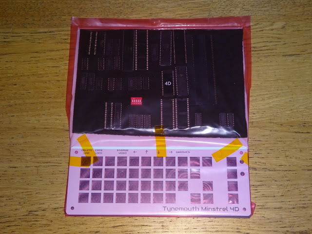
And finally, in the third bag, the perspex parts and printed materials.

I know most people will want to jump straight in, but it is worth having a read of the manual first. That should contain all the information you need to build the kit.

As well as build instructions, there is a lot of information about using the kit, and schematics with detailed descriptions.

Of course, if you prefer, you can just look at the pictures here.
One section you should take a look at is the parts list.

With any kit, it is a good idea to start by going through all the parts so you know what is what.

You don't need to knoll all the parts out like that, but I like to, and it is useful to take a photo of what was in the kit when it arrived, so when you can't find a bit later on, you can check to see if it was actually missing, or if it just fell on the floor.

The ICs are presented on the black foam relative to where they fit on the PCB, so that part is done for you.

Also done for you is soldering the SD card socket. No only because it can be tricky if you are not used to that sort of thing, but also because the socket would be quite fragile if not already soldered to the PCB.
The manual takes you through the process step by step, with colour coded parts marked on the PCB diagram.
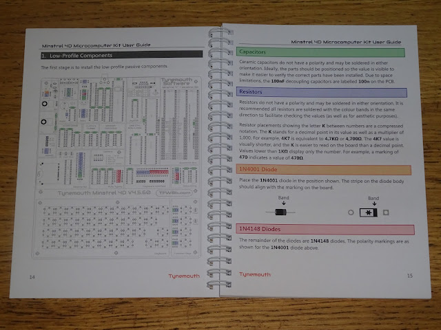
Take this slowly, each part value is marked on the PCB, so just match that to the markings on the part and solder them to the board. For parts like the capacitors where it is not easy to tell them apart, the quantities are deliberately different, so the one where there are loads of them will be the 100nF. The one with only two parts on the tape will be the 22pF and so on.
I like to use one of these leg benders to make sure all the parts fit neatly into the spaces on the board.

All the diodes and resistors are at 400 mil spacing (0.4"), as are all the capacitors except those decoupling the smaller ICs, which are at 300 mil (0.3") spacing.

There are various ways to solder these parts on. Most people hold each one in place, turn the board over and solder from the back.
You can also get jigs where you install some parts, the fit a cover on the front of the board to push down on the part, then flip it over and solder the legs from the back.
I do it differently. I haven't seen anyone else do this, and when I posted these photos on my discord (see the end for a link to my Patreon where this is available), it seemed to provoke some debate.
This is the high-tech jig I use to build a board like this.

I balance the PCB on the edge of a shelf and weigh it down with a reel or two of solder. I normally use the thicker 1.2mm stuff to weigh it down, as we all know that a 500g reel of 1.2mm solder must weigh more than a 500g reel of the thin 0.7 mm stuff....
With the board like that, I drop in all the through hole parts from the top, all in one go (apart from the few down the side of the keyboard which are currently blocked by the shelf).
Points will be deducted if all the resistors not in the same orientation, although that is purely for aesthetics and ease of checking you have the right parts in the right places. Same with the capacitors, if you can bend and orient them so the writing with the value is visible from the top, it will make it easier if you have to troubleshoot later on.
The diodes have been arranged so that they are all the same way around, and it is important for it to work correctly that they are inserted that way around.

I find this is faster, and easier way, and gives a better result. You may disagree, but I would encourage you to give it a go, but maybe start with something smaller than a Minstrel 4D.

Don't worry about all the legs touching below, you don't need to go anywhere near them with a soldering iron.

All the soldering is done from the top of the board. I think that also gives a neater appearance, as you can make sure all the joints are soldered evenly, as these will be the ones you see, not the back of the board.
Once they are all soldered, you can turn the board over and cut off all the legs in one go.

I still tend to keep all the cut off legs even though I have several large boxes full of them that I will never, ever need. Still might come in handy one day........

After those are done, I repeat the process for the parts on the side of the keyboard which I couldn't get to before.

And that is all the resistors, axial capacitors and diodes done, time to turn the page on the manual.

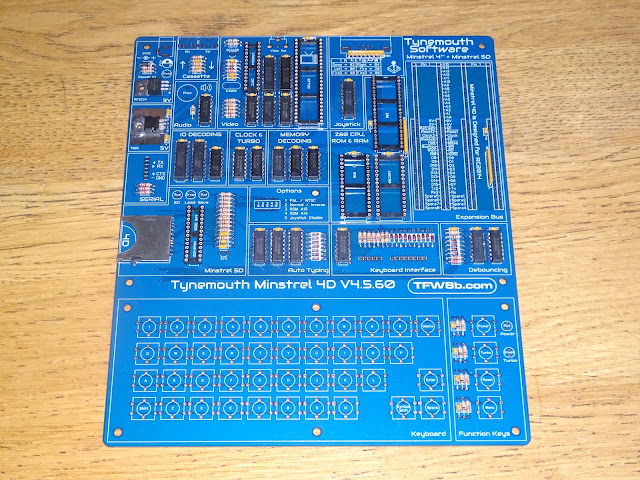
Next in height order are the ICs, sockets and resistor arrays. The kit comes with sockets only for the larger chips. You can fit your own sockets for the smaller logic chips if you like, turned pin ones would be recommended if you do that.

The ICs are arranged on the foam pad in approximately the same layout as the board itself, so it should make locating the correct parts easier.

You will find it easier to slide the chips into the board (and indeed into sockets) if you bend the legs slightly so they are vertical.

I use the same high-tech approach to fit the non-socketed ICs, two reels this time, to counterbalance the additional weight of parts. This is proper 60/40 tin/lead solder, obviously, not the lead-free rubbish. Lead solder is better, and of course two 500g reels of lead solder will be heaver than two 500g reels with the absence of lead........ (yes, I have now made the same bad joke twice, and will continue to do so until someone laughs at it)

Once the ICs are in place, I solder the legs on one or two corners of each chip to hold them in place (often the ground pin as that doesn't always flow through to the top side due to the extra thermal mass of the ground plane).

Once the corners are all done, I turn the board over and solder the rest of the pins. I fit IC sockets in a more traditional way, holding them in place and soldering from the back, as there is nothing to solder from the top.

All three resistor arrays are the same, and pin 1 is marked by a dot on the package, and by a square pad and white box on the PCB silkscreen.
Don't install the ICs in their sockets just yet, leave them in the foam for the moment.

Next comes the two TO220 packaged devices, the MOSFET and 5V regulator.

The legs should be bent as shown in the manual, at the knee, not right at the package.

I normally rivet these in place, you can do that. Or you can bolt them down.

You can even add a heatsink to the 5V regulator if you plan to add lots of RC2014 cards. The MOSFET should never get warm, so does not need a heatsink (also note, the tab of the regulator is at 0V and the tab of the MOSFET is at 9V, so don't bolt them to the same bit of metal!)

For the purposes of these photographs, I will go for the simplest option of soldering them down. You might need to turn up the heat on your iron for this bit if the solder doesn't flow properly on the large metal tabs.

That's those done.
Next, the crystal, piezo and DIP switch.

After those, the taller parts, the LEDs, TO92 packages and the electroyltic capacitor.

The orientation and polarisation is all explained in the manual.

The LED shapes on the PCB should give you the correct orientation (also short leg = square pad).

Next the connectors. These should be straightforward, the only bit of advice is to use some spare pin headers to help keep the RC2014 sockets vertical.

They are spaced 600 mil (0.6") apart, so you could also use ICs for spacing, but pin headers would be better.

I normally clean the board at this point, as that is all the soldering done (usually anyway).

I use Pro Power flux remover from CPC/Farnell to break up the flux residue, and then some IPA to clean all that off. I haven't taped over the names to hide the brand, it is just that I have quite a lot of their spray cans, and they are all blue with white bits, so I put different coloured tape around the top so I can more easily spot which is which.

Time to give this a good check over for solder bridges, missed solder joints, parts in the wrong place etc.
In order to test, don't fit any of the socketed ICs yet, just fit the power switch. No need to solder these in place, it just clicks in. (if you fitted sockets for all ICs, you only need to install the 4013 and 40106 next to the power switch to test powering on)

Plug in the 9V centre negative power supply and check the green LED near the power socket comes on. If it does, press the power button and see if the red power LED comes on.
If you have a multimeter, check the voltage between pins 16 (bottom left) and 32 (top right) of the ROM or RAM socket and make sure it is reading 5V.
If there are any problems, turn off and check over the board again.
Next, insert the remaining chips into their sockets, noting the 4D ROM chip aligns with the bottom of the IC socket. You can also fit one more key, T, you will see why shortly.

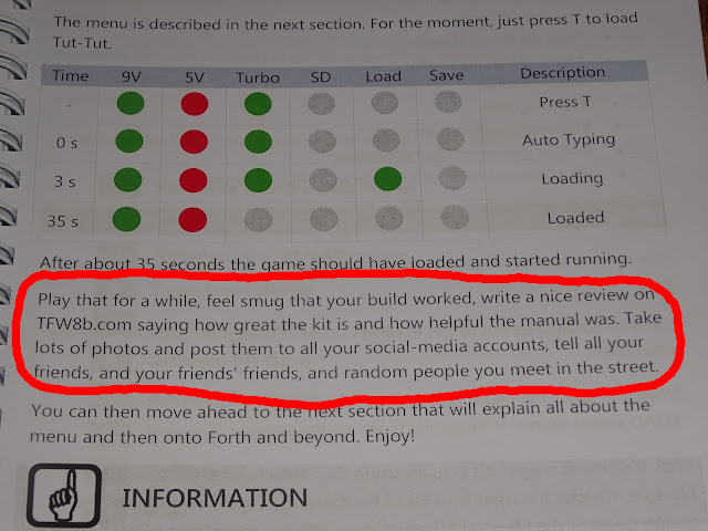
Plug in a monitor to the composite jack, plug the power back in and switch it on, and you should be greeted by the menu (after it has loaded, anyway).

Again, if you don't see this, turn off and check over all the parts.
If it has worked, go on, press the T key.

All being well, Tut-Tut should load, and if you plug in a joystick, you should be able to have a few quick games before moving on.
I can only echo the wise words of the manual at this point.
Yes, it's keyboard time.

This can be a slow process, but just put on a good box-set or your favourite YouTuber and get on with it.

Start with the key switches first, the four on the right are the yellow ones that are a little harder to push, for the function keys.

Start but cutting out all the 10mm x 10mm squares from the keyboard sheet. There are three copies, so you get a couple of chances if you go over the lines.

Each key is the same. Take the paper square, a white cap and a clear cap.

Insert the paper face down into the clear cap.

Push the white cap on top of that, again face down.

And finally you have your keycap. One down, 44 to go. (don't worry if you have one or two spare at the end, I erred on the side of caution when counting / weighing the kits out).

Once they are all done, use the spare key artwork (or the page in the manual) for reference and click them into place on the switches.
Loosely fit the white keyboard overlay PCB using the pillars as shown. Don't tighten the top screws so it can move around a bit as you fit the key caps.

Once that is done, time to give it a test and make sure all the keys work (and are in the right place).

I don't normally solder the keys in place, they make good contact just as they are, but you can if you want. This particular order is destined to go overseas, so I have soldered them on this occasion to survive shipping.

Yes, I did spent far too long lining up the screws and pillars for that photo. Again, there maybe one or two spare screws, but no one should be short of anything.

Finally, time to fit the perspex top and bottom plates, and don't forget to peel the protective film off other sides.

The finishing touch is the feet on the bottom sheet of perspex.

And then you're done.

Doesn't it look good?
You can just keep looking at it, but after a while you will want to plug it in and try it out more.

See the manual for correct setting of the DIP switches, but all switches off will work for most people.

It is the law that you have to start by typing vlist, to display the FORTH vocabulary list.

Now you can try out all the other features, you can add RC2014 modules such as this AY-3 sound card.

Or load games from SD card or even tape if you want.

Vintage Jupiter Ace tapes should work, and there are even a couple of modern ones for the Ace and Minstrel 4th (the Minstrel 4D is derived from the Minstrel 4th, so is fully compatible). Including the recently released 3D Monster Maze.

Rex lies in wait.......

Advertisements
Minstrel 4D
The Minstrel 4D kits are shipping now, you can order one from The Future Was 8 bit
https://www.thefuturewas8bit.com/minstrel4d.html
More info in a previous post:
http://blog.tynemouthsoftware.co.uk/2022/08/minstrel-4d-overview.html

Patreon
You can support me via Patreon, and get access to advance previews of posts like this and behind the scenes updates. These are often in more detail than I can fit in here, and some of these posts contain bits from several Patreon posts. This also includes access to my Patreon only Discord server for even more regular updates.
https://www.patreon.com/tynemouthsoftware
