
This is a bit of an unusual modification you could do to your BBC micro back in the day.

It turned an early 1980s all in one computer into a late 1980s computer with a separate keyboard and twin disk drives.
It is quite clever in that it reuses the base half of the BBC micro, and just replaces the top of the case.
The new top parts tend to be very brittle plastic, and many of these just collapse as the drives sort of hang off the top of the case and pull it apart.
Here it is still intact, just, although all of the switches on it are missing or broken.

Inside, however, is the standard BBC micro. And as with any BBC micro, the important things is:
DO NOT PLUG IT IN UNTIL YOU HAVE CHANGED THE RIFA CAPACITORS!
These things are well known for going bang and giving off a could of pungent smoke, in a very alarming fashion.
Many will do this at first power up. Sometimes they will lull you into a false sense of security and not go bang for several hours. But they will go bang. They all do. Do not risk "I'll just plug it in for a quick test first". I learned that lesson a long time ago.
Ask me how I know.
So, step one has to be to dismantle the unit and replace the Rifa brand mains filter capacitors in the power supply.
That is not easy for several reasons.
Getting into the Viglen case - this is a little more convoluted than normal, and you have to deal with the permanently attached keyboard when you flip it over. When you get the case halves separated, you also need to disconnect the disk drive power and data cables, and also the speaker cable, before you can detach the top section.

Once the top section is removed. You have the original BBC micro base, just without a keyboard. Although, you never know what you are going to find plugged into a BBC micro. In this case an ATPL Sidewise Sideways ROM/RAM board that allows you to add 11 ROMs and 1 bank of sideways RAM.

Removing the power supply is a little move involved on a BBC, as instead of a single power connector (like pretty much everything else), this one has seven separate small spade fittings.

The next problem is the ROM/RAM board. This covers over two of the power connectors.
Removing the ROM/RAM board - Like many boards of this type, it is mounted with pins sticking into two IC sockets on the board. The OS ROM top left of that picture, and the ADC bottom right.
Easing those pins out of their sockets it is clear there have been in and out many times, and some of the pins are a bit bent, and I imagine it will be quite a struggle getting it back.
Not so fast though, as there are two more connections to a jumper below that need to be unplugged.

There is also a switch wired to the top of the board, that needed to be removed. That looks to be shorting out bits of the econet circuitry? Luckily I didn't power any of this on.
Remove the PSU - Once the ROM RAM board was removed, I could get access to the last two connectors. They did not detach as normal. It seems that to fit the ROM/RAM board, these had been cut down and the ends soldered direct to the tabs.

Repairing the Power Supply - Once the supply was actually removed, it was just a case of the usual procedure I am sure I have covered several times (e.g. http://blog.tynemouthsoftware.co.uk/2019/06/bbc-micro-issue-3-model-b-repair.html). These are not nice supplies to work on, you have to unclip the mains switch and the auxiliary connector and usually takes quite a bit of work to get both pushed through and the spade connectors removed from the mains switch.

In this case, I also removed the mains cable, as the mains plug was very manky, and has unshrouded live and neutral pins.

Once all that is removed, the board can be extracted.

You can now get a proper look at the two Rifa brand mains filter capacitors, the yellowy boxes marked 0.1uF and 0.01uF.

And, as is usual, they are both showing signs of cracks, and one has previously ruptured. If you have any equipment with these in, do yourself a favour and replace those before they get angry.

As well as those, I also replace a 220uF capacitor which has a habit of drying up and causes the supply to fail to start up. It is worth replacing that whilst the board is out.
All the other electrolytics look fine, so I see no real need to replace them.

It is then a case of the painful process of putting it all back together.
I didn't want to solder the old lugs back to the board. I never like having things soldered together than you have to desolder whenever you want to take them apart.

I replaced the two soldered mainboard power connectors with 0.1" header connectors, and moved the two sleeves to the final two connectors that were missing those.

To fit the matching connectors, it is out with the main board, but wait. The BBC has an odd video connector that looks like it was designed to take a PCB mount socket, but always has a panel mount BNC socket with short wires soldered to the board.
Remember what I was saying about not liking things soldered together....
What I usually do is fit 0.1" pin headers here as well.

The whole machine was a little grotty, with various things having lived in it at some point, so it was a good opportunity to give it a good clean out.
Putting it back together
Time to put it back together.
First the base.

Then the mainboard. A standard Issue 7 BBC model B board. The latest and most widespread version.
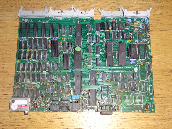
The power connections that were soldered have been replaced by right angled 0.1" pin headers, so they will fit neatly under the ROM/RAM board.

The data cable for the disk drive is normally accessible under the machine, but for the Viglen case, it needs to be sent back into the case, so that has to be done when installing the board.

The disk drive power and data cables both loop back into the machine. The round grey wire is the keyboard cable.

The Power supply can then be reinstalled, the new power connectors seem to work quite well.

And there is the mainboard and power supply reinstalled.

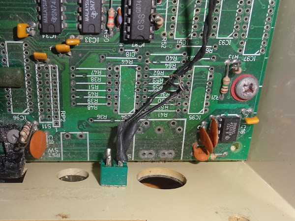
I fitted a replacement switch and wiring at the back of the case, this is the write only switch for the sideways RAM in bank 15.

Before first power on
It is important to have a keyboard connected to a BBC, or it won't boot. I am sure many people have fallen for that problem before. It is actually easier on the Viglen as the keyboard is on the long curly cord, rather than the short cable on a normal BBC.
I was sure I had built a "keyboard emulator" in the past, just some pullup resistors and a power LED. There is also a caps lock switch and LED to test that pressing that toggles the LED to show things are running as normal even if the screen is blank.

I eventually found it, but it didn't look right for the BBC pinout?
It took me far too long to remember that I actually made it for an Acorn Electron (which has a similar requirement for the keyboard to be connected).

I carefully put that back into the "Electron Bits" box and just plugged the Viglen keyboard in and moved on.
In order to test things, I tried running it without the ROM/RAM board at first. In theory, all that was required was reinstalling the OS ROM and the ADC, and fitting a jumper where the two wire connection had been installed.
First power on

Excellent, that is as expected. The OS ROM is running, but there are no language or filing system ROMs, but it boots up, and the voltages measure correctly
However, it's not responding to keys, and the power on beep isn't stopping.
That is usually down to the system VIA, the one next to the keyboard connector. This lives under the ROM/RAM board, so I was pleased I found that before I refitted it.

I swapped it with the user VIA (the one next to the user and printer ports), and that fixed the problem.
I fitted a new W65C22N in place of the user VIA.

Time to refit the ROM/RAM board.
Reinstall the ROM/RAM Board.
The pins on the board are anything but straight. I can imagine it will be a nightmare getting these back into the sockets. I wasn't 100% convinced all the pins were in the right place before.

My solution to this is to carefully push on a turned pin socket. This took ages to get those all aligned, but once it's on there, hopefully they will stay there and keep the pins protected and aligned.

It does raise it slightly, but there is enough space in this case. It should add a little more airflow space for the chips below as well.

I refitted that with the minimum of just the BASIC ROM and the two RAM chips which form the sideways RAM in bank 15.

But it didn't boot.
I checked over all the connections, and all looked OK, so I tried it without the BASIC ROM and I got the Language? prompt again.
I tried a spare BASIC ROM, and it then booted up.

Back to the original and it did not, so I think the BASIC ROM is toast. I burned a new one and that also worked.

I went through the rest of the ROMs, trying each one in turn, to see which ones worked, and which ones were any good.
I burned a copy of Advanced Ron Manager to help with that.

But all it said was "jumpers for goalposts, isn't it? wasn't it?"
So I burned a copy of the Advanced ROM Manger instead and that was much more useful.

I had found a label in the case, so I knew one of the unmarked ROMs was "Wordwise".

Once I found it, I made a new label for it in the appropriate font.

This was the collect of the ROMs I think are useful. I left out the ones I didn't recognise, or didn't work. ARM's *ROMS command lists those as follows

SD2BBC
The blue labelled ROM at the bottom is the Smart SPI ROM for the Future Was 8 bit SD2BBC.
https://www.thefuturewas8bit.com/shop/bbc/sd2bbc.html

The adapter for that plugs into the user port, and the cable runs out the side.

The box with the SD card can then live beside the unit, or can be routed inside the case if you prefer.

Shift + Break will load the menu, and of course, all you need to do is type 46 to get to page 46 of the menu of games, and then L and return to load Repton.

It's a hard job testing through Repton, but someone has to do it.
There was going to be a second post on the disk drives next.

I replaced the two broken 40/80 track switches, although it is not clear how the labels apply. The left hand switch is drive 0/2, and the right hand 1/3. So maybe when switched to the left is 40 track and the right is 80 track?

However, whenever I plugged either drive in, it will not power on.

Not sure what is going on there.
I don't like leaving a job incomplete, but I ran out of time, and had to get this back to it's owner, so I have left them disconnected for the moment.
It was enough work putting it all back together. The drives need lots of fettling of spacers and screw adjustment to sit level. I didn't go the whole way to getting them fully level as I think they have someone else lined up to take a look at them, so they are going to be taking them out again to fix them anyway.
Advertisements
SD2BBC
The SD2BBC with the cable, connector and ROM chip are available to order from The Future Was 8 bit.
https://www.thefuturewas8bit.com/shop/bbc/sd2bbc.html
Some examples of fitting / using these in previous posts:
http://blog.tynemouthsoftware.co.uk/search/label/SD2BBC

Patreon
You can support me via Patreon, and get access to advance previews of posts like this and behind the scenes updates. These are often in more detail than I can fit in here, and some of these posts contain bits from several Patreon posts. This also includes access to my Patreon only Discord server for even more regular updates.
https://www.patreon.com/tynemouthsoftware
