Sunday 25 August 2024

Another monitor repair

I don't know what it is about old monitors recently I seem to be having bad luck. I had another one start to flicker. Usual problem, failing capacitors in the power supply.

This Acer from December 2007 also seemed to be unnecessarily difficult to service.

Everything behind metals panels.

And then the boards are upside down, but you can't just take out the one with the capacitors on.

There are captive cables soldered at one end that you can't get the other side of to unplug, just like the Phillips one I did previously - http://blog.tynemouthsoftware.co.uk/2024/06/annoying-lcd-monitor-repair.html

I don't think anyone will be surprised to see several caps with their vets bulging at the top.

I don't know if they deliberately place the capacitors right next to the heatsink to ensure they fail so they can sell you a new monitor in a few years time*. They don't need to be there, the traces run up to the heatsink for no reason, they aren't connected to any of the devices attached to it.

* OK, these lasted from 2007 until 2024, but let's not split hairs

Take the two green ones for example. They are both marked 1000µF 10V. One almost touching the heatsink, and one set back slightly.

The one away from the heatsink was sort of OK, 90% of rated capacity.

The other one that was almost touching the heatsink was down to half of it's marked capacity. Same age, same brand, same ratings.

The big one at the other side of the heatsink wasn't even bothering anymore.

Time for the replacements. Something you don't often see when people are recapping things is testing the new parts. Are they actually any better? (in some cases, I would argue they are not, but let's not get into that).

You can often get better choices by going for physically larger capacitors, and that usually means going for a higher working voltage than originally fitted.

In the case of the two 1000µF 10V caps, I tried two options. The first is the ones I normally use these are "low ESR" capacitors, and rated for 105°C use.

0.16Ω isn't bad for ESR (the lower the better), and the capacitance is 1062µF, so a touch higher than the rated value of 1000µF, which is good.

Stepping up to a 16V capacitor, that also reads a bit high in capacitance terms, but does even better in terms of ESR. However those are only 85°C rated, and these things are unnecessarily close to the heatsink as previously discussed, so I went for the 105°C rated parts.

The replacement for the larger one looked like it would be too tall, so I fitted a larger axial one on it's side. Which also has the benefit of moving it further away from the heatsink, so should extend it's life futher.

Another monitor resurrected.


Advertisements

I don't sell 20 year old monitors in my store, but I do have the full range of Minstrel and Mini PET accessories. Mini PET kits are all sold out now, but I do still have some Minstrel 3 kits left, which will last until I run out of Z80s.

I can ship worldwide, use the link at the top of the page to contact me with your location and what you want. Sorry I have to keep saying that. I am working on an alternative.

All the links can be found here:

Patreon

You can support me via Patreon, and get access to advance previews of posts like this and behind the scenes updates. These are often in more detail than I can fit in here, and some of these posts contain bits from several Patreon posts. This also includes access to my Patreon only Discord server for even more regular updates.

Sunday 18 August 2024

Salvaging 18650 Cells

This was going to be a part of another post, but it has grown, as they tend to, into a post of it's own. Look out for the project itself in the coming weeks.

As part of an upcoming project, I needed a power source, and a good choice theses days are 18650 cells.

These are Lithium Ion cells 18mm diameter, 65.0mm long. 3.7V nominal, but up to 4.2V when fully charged. (did you know that is the same naming scheme as coin cells, 2032 is 20mm diameter, 3.2m thick)

They are being used in an increasing number of things, like solar lights, power banks and vaping devices. There are lots available online, and as usual with things like this, they often come with hugely optimistic capacity markings from far east sellers and local resellers. ("oh, 4000mAh is the part number")

You also find them in those cheap USB power banks, although those are often quite low capacity cells.

Another well known source of these is old laptop battery packs, and I have rather a lot of those. So when I need some more 18650 cells, I dig one of those out to scavenge.

A lot of old laptop batteries are composed of 18650s, you can usually tell by looking at the sizes and ratings.

In this case, the battery pack is just wide enough to contain an 18650. The voltage is 10.8V, so they are using 3.6V as the nominal voltage instead of 3.7V which is more commonly used these days. Three 3.6V cells in series is 10.8V.

Looking at the size of the pack, it is probably three sets of three cells in parallel (3s3p), 3.6V 1200mAh per cell giving 10.8V 3600mAh in total.

1200mAh isn't great. Modern cells are often three times that. Still could be useful for some applications (super long battery backup maybe?). But I'll leave that for another day.

Ah, this one looks more like it.

Looks like it is the right size to be six cells. 11.1V @ 4400mAh, would be three pairs of two cells (3s2p), 3.7V @ 2200mAh each. That sounds decent enough, and the laptop these were for is long gone.

Now, the warning. Lithium Ion cells are dangerous if mishandled. They can explode or catch fire if you short or pierce them. Be very careful, use plastic tools, separate the cells as soon as possible. If in doubt, don't.

This pack is probably 20 years old, so the plastic is quite brittle, and easy to start to snap bits off by hand.

Result! Samsung branded 18650 cells. (well, at least they have Samsung printed on them)

Six of them as predicted. You can see how they fill the pack. The only other thing in there is the battery management board.

But we don't need that anymore.

What we do need is the six cells. You can see here how the three pairs are connected in parallel then series. 3s2p, three series sets of 2 cells in parallel.

Those are joined by strips of nickel spot welded to the ends. Those break off quite easily and you end up with six individual 18650 cells.

Samsung ICR18650-22B would seem to confirm the 2200mAh calculated above. 615 may be a date code? 15th week 2006 sounds about right.

These differ slightly from standard cells in that they don't have the pip at the positive end, so they may not fit every application.

But you can still tell the difference from the negative end.

Note some cells have a small board at the end which is a protection circuit to prevent over voltage and over discharge. The ones in the packs do not usually have those.

It depends on your application, but these fit fine in 18650 battery holders. (I know one cell doesn't count as a battery, but they are still called battery holders)

It is not advisable to solder directly to the cells, you could try to leave some of the nickel strips attached and solder to those, but you have to be extra careful not to short things out if you leave those attached, so try to avoid that. You can buy the nickel strips and miniature spot welders from ebay or ali express if that's your sort of thing.

Time to test these out. First step is to measure the voltages and reject any dead cells. Anything above 2.5V seems to be salvageable, if the voltage is really low, the cell may have failed and you should probably reject it.

I use one of these cheap chargers from Amazon, seems to do a decent job. I am using the lowest charge rate this one supports, 500mA. These cells started out around 3V and quickly rose to about 3.5V and kept going.

Monitor them carefully to see if any are getting hot. I don't think this charger has any thermal cutout, so keep checking nothing is getting hot.

After an hour, they had all risen to about 3.9V, so were charging well.

And after 3 hours they were over 4V.

The charging cut off is 4.2V, which they reached after 4 and a bit hours.

Most of the cells had taken between 2100 and 2200mAh. They have been in a box for about 10 years, so would have been very flat. But that seems to confirm these are 2200mAh cells.

I repeated with the remaining two cells, which both performed perfectly as well.

These cells all behaved impeccably, but sometimes you get ones that appear to charge very quickly, but you put them in a torch and it goes dim after a few minutes. Again, you can reject those.

A powerful torch is a good test load. This one is optimistically rated 10W, but is probably more like 2. I ran one of those cells for half a day until it started to go dim, and then it took a full charge, so all looking good.

The next day, they are all still reading a bit under 4.2V. If any of them drop significantly in storage, then you should probably rule those out as well.

So far, so good. Six "free" 18650 cells, ready to use.

Find out what I have planned in an upcoming post, or subscribe to my Patreon (link below) to get an advance preview.

Advertisements

I think I still have all the kits in stock, but I am down to only a few of each type of kit left, some are the last ones.

The SellMyRetro store is also on it's last days, everything is still listed there if you need more information, but best to use the contact me link about, tell me what you want and where you are and I will send a PayPal invoice. Sorry I have to keep saying that. I am working on an alternative.

All the links can be found here:

Patreon

You can support me via Patreon, and get access to advance previews of posts like this and behind the scenes updates. These are often in more detail than I can fit in here, and some of these posts contain bits from several Patreon posts. This also includes access to my Patreon only Discord server for even more regular updates.

Sunday 11 August 2024

Last of the Minstrel and Mini PET kits

I am currently looking at options for how and where to sell my products (suggestions welcome).

As part of that, I have been checking stock, and I seem to be running out of everything. All the main kits have been hit by parts being discontinued.

The Mini PET kits need dual port RAM chips and microcontrollers that have been discontinued. I now only have a few of those left.

The Minstrel 2/3/4th kits need Z80s, which have also been discontinued, so they will only last until I run out of Z80s.

Whenever I run out of anything I inevitably get emails along the line of "I just missed out on getting an X, when will they be back?" Don't be that person. I have been selling these for nearly 10 years now, don't say you haven't had a chance.

The Mini PET would need a radical redesign to get around missing parts, but I don't think there is much I can do with the Minstrel kits when the Z80s run out. Maybe a prebuilt eZ80 based version, although I don't think it will be compatible enough to work. I should investigate that at some point.

I am also running out of PCBs, but there doesn't seem any point in ordering any more as I don't have the parts to make more kits anyway.

I was looking around to see what I had left, and found another pack of boards.

Great, they are Mini PET B boards. There was only one of those left.

Oh, I must have ordered a new set with the new style logo. Don't remember doing that.

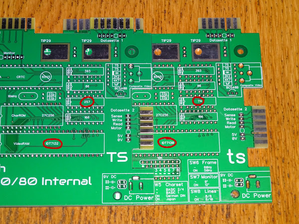
Oh right, so these are not Mini PET B boards, which are 40 column only, these are Mini PET 40/80 Internal.

I think I vaguely remember that.

(at this point I was planning to insert some history, but it's all a bit cloudy, and well, wait and see, I will put that in later)

Looking over the board, the left hand side, the PET address decoding and IO chips are the same (I am working on a post about PET address decoding, coming soon, lots of diagrams to draw).

The changes are on the right.

Things look the same, but there are some part changes and quite a few traces are re-routed.

The 74HC74 has been replaced by a 74HC257, and the 7130 1K dual port RAM is now a 7132 2K dual port RAM.

The contents of the system ROM, character ROM and the micrcontroller are different though. The microcontroller was completely rewritten for the 40/80 systems.

The character ROM is also different as the original was like the PET, 128 characters, with hardware inversion. To save a flip flop and because the character ROM is mostly empty, I changed to storing the inverted characters in ROM as well, so all 256 could be selected directly from ROM, which simplified the video output circuitry. (avoiding the need for the character invert flip flop and the pixel synchronisation flip flop, since all pixels were generated in the same way at the same time)

I also seem to have moved the DIP switches, Ready LED, piezo and monitor connector, and also relocated a 1K resistor. I can't resist tweaking things.

I think I had better build one up. 

I had to steal most of the parts from one of the other boards to try it out.

Time to give it a go.

Yay, it works!

Time to try out the party piece, 80 column mode. Unlike the stand alone 40/80, in this case I think 80 column mode is set via a DIP switch.

It didn't work.

I tried various ROM sets and DIP switch options, but it was firmly stuck in 40 column mode.

I dug out the schematic to find out what was going on.

The ROM images on the Mini PET are all 32K. There are 4, 8 or 16 of these are combined together to make the Mini PET ROM, with the appropriate image selected by the top address bits of the ROM chip.

On the normal Mini PET 40/80 with a built in normal / graphics keyboard, there are two DIP switches to select the ROM set, and the 40/80 mode is the third ROM select, giving a choice of 8 images. Seems sensible since 40 column ROM sets won't work in 80 column mode etc.

For the "B" models that fit in a PET case, there needs to be another 8 ROM images, the same as the first 8 but with the editor ROMs for business keyboards.

That extra address line means I would have to use a 27C080 ROM chip rather than the normal 27C040. (dollar signs spin around my eyes at this point, specially the prices these days).

However for testing I can use the normal ROM as the A18 pin is not connected on the normal 27C040 ROM, so will be ignored and I will just have to set switch 3 to match 40 or 80 column mode.

So why didn't it work?

Then I spotted the problem.

Can you see it?

Well, there are two sorts of switch arrangement used there. Look at switch #1, that is driving a ROM address line. When off, the resistor array pulls that down to 0V. When on, it is switched to 5V, giving the desired 0 or 1 for the ROM address.

The second type feed the microcontroller to set the video options. Look at switch #7 for example. The microcontroller inputs have an internal pullup, which pulls them high normally, and are switched to 0V.

Did you spot the problem yet?

It looks like I was in the process of changing things around. I suspect I may have been moving 40/80 column mode to switch #10, or to switch #6. Either way, I it is only half done. Switch #10 (video option 4) is pulled up to 5V, or can be switched to 5V, so will always read a 1. Switch #6 (40/80 column) is pulled down to 0V, or can be switched to 0V, so will always read a 0.

I probably had a phone call or a knock at the door at just the wrong moment and must have forgotten where I was up to when I got back to it.

A quick bodge and it's functional. I have disconnected the pull down on the 40/80 line and solder-blobbed it to ROM_A17 on the ROM, so switch 3 now controls ROM A17 and 40/80 mode, just as it does on the normal Mini PET 40/80.

I should also fit a wire from switch 10 to one of the spare pull down resistors.

And there we have functional 40/80 column mode, and it can also be switched back to 40 columns with the DIP switches.

Well, at least it working, although it means I can't sell these boards as a kit (not that I have the parts to do that anyway).

Maybe I can list this as a one off prototype - Anyone want to buy a Mini PET Internal 40/80 ?

Now, I promised a history section, here it is.

When the Mini PET started, there was only one version. The same board could be built for PET case or bench with a slightly different set of parts. Later I got some boards made in green to make the distinction clearer.

Later still the green board was expanded to fit better in the PET case and add in support for the PET power supply (which was original a separate board).

When I was looking for that photo (I had called it A+B, so it didn't come up in the search for Mini PET), I found this photo.

It was at this point that I noticed the writing on the larger board.

Hang on, that's one of the ones I had just built?

So I did build one of these before?

And then I found another photo, this time with the 40/80D, the pre-assembled version with the built in SD2PET.

I think that explains why I did not progress with these boards.

When TFW8b was selling the Mini PET 40/80 and the Mini PET 40/80D, I had agreed to stop selling the Mini PET kits so as not to compete with the TFW8b versions, and I only brought them back after TFW8b sold out and decided not to do anymore.

So I built one of those back in 2020 or 2021, although I have no idea what happened to it.

It worries me when I look through at photos from only a few years ago and find projects I had forgotten I had built.....

... oh, OK, yes, I guess I must have done an "A" version as well.

That I think is an earlier prototype as it has 5 chips on the right, so presumably still has the hardware character inversion I talked about earlier. (and the older logo)

I do remember doing a board with a slide power switch (I didn't like it).

I think that was what led to the soft power on functionality of the production 40/80 kits.

Seems like I am running out of everything at the moment, even memories.....

Great chunks of my past, detaching themselves like melting icebergs......

I am being diminished. Whittled away, piece by piece.

A man is the sum of his memories, you know. A Time Lord even more so.


Advertisements

I think I still have everything in stock, but I am down to only few of each type of kit left, some are the last ones.

The SellMyRetro store is also on it's last days, everything is still listed there if you need more information, but best to use the contact me link about, tell me what you want and where you are and I will send a PayPal invoice. Sorry I have to keep saying that. I am working on an alternative.

All the links can be found here:

Patreon

You can support me via Patreon, and get access to advance previews of posts like this and behind the scenes updates. These are often in more detail than I can fit in here, and some of these posts contain bits from several Patreon posts. This also includes access to my Patreon only Discord server for even more regular updates.