All of the Commodore PET series of computers have an IEEE-488 port, used for disk drives and printers. (I checked all of my PETs, and none of them seem to be labelled, but imagine it says IEEE-488 over that port)
There are quite a lot of elements that go to making up the port on the, and thus many things that can go wrong. It is a parallel 24 pin bus, with 8 data pins, and 8 handshaking lines, and 8 ground pins.
Close by the port, there are three MC3446 buffer chips, and next to that a 6520 PIA. You might think that with more than 16 IO pins, that 6520 would be enough to drive the port, but that's not the case. It is arranged so that each pin on the IEEE-488 port is connected to two IO pins, one to drive the pin, one to read the values, so as well as all the pins on that 6520, it also uses a number of IO pins on the other 6520 (near the keyboard connector) and the 6522. REN is not used, the PET is always going to be the bus master, and IFC is only an output, SRQ only an input.
Signal
|
Read
|
Write
|
DIO1-DIO8
|
PIA#1 PA0-PA7
|
PIA#1 PB0-PB7
|
EOI
|
PIA#2 PA6
|
PIA#2 CA2
|
DAV
|
VIA PB7
|
PIA#1 CB2
|
NRFD
|
VIA PB6
|
VIA PB1
|
NDAC
|
VIA PB0
|
PIA#1 CA2
|
IFC
|
N/C
|
Reset buffered through 7417
|
SRQ
|
PIA#1 CB1
|
N/C
|
ATN
|
PIA#2 CA1
|
VIA PB2
|
REN
|
N/C
|
Tied low
|
In the above table, there are three main chips referred to PIA#2 is the 6520 nearest the keyboard connector, PIA#1 is the other 6520, nearest the IEEE-488 port, VIA is the 6522, usually between those two. The IEEE-488 bus is one part of the PET which didn't change from the 2001 up to the 8032, and with a few minor changes onto the later CBM-II machines.
This two way circuitry does make it possible to do quite a lot of testing from the machine itself. If you read back the value of a pin, then change the machine output and read it back again, you can see if it has changed. The 8 data bits are the easiest to start with, whatever value you write to address 59426 is written to the port, so
POKE 59426,0
will set all the outputs low. A word on states and levels here. Writing 0 to one of these outputs pulls the bus line low, this is the 'asserted' signal, and means it is active. When no device is asserted, the signal is pulled high by pull up resistors, 'released' to high. Nothing will ever drive the bus high, all they do is let it float or pull it low. To read it back, type
PRINT PEEK(59424)
That should show 0. If it does not, there is a problem with PIA#1 or one of the MC3446 buffers. You can then try various other values up to 255 which should have all the output lines high. Testing other pins is a little more complicated, this table shows the values to poke and peek at.
Pin
|
Write 0 (Assert)
|
Write 1 (Release)
|
Read value
|
DIO1-DIO8
|
POKE 59426,0
|
POKE 59426,255
|
PRINT PEEK(59424)
|
EOI
|
POKE 59409,52
|
POKE 59409,60
|
PRINT PEEK(59408)
|
DAV
|
POKE 59427,52
|
POKE 59427,60
|
PRINT PEEK(59456)
|
NRFD
|
POKE 59456,255
|
POKE 59409,253
|
PRINT PEEK(59456)
|
NDAC
|
POKE 59425,52
|
POKE 59425,60
|
PRINT PEEK(59456)
|
ATN
|
POKE 59456,251
|
POKE 59456,255
|
PRINT PEEK(59425)
|
This can be useful to identify which pins are working, and any at fault, but it doesn't show if the problem is the output pin (or it's associated buffer) failing to drive the output low, or the input pin (or it's associated buffer) failing to read back the state correctly. You can check this with a multimeter on the pins of the port, but I have built a board to make that easier.
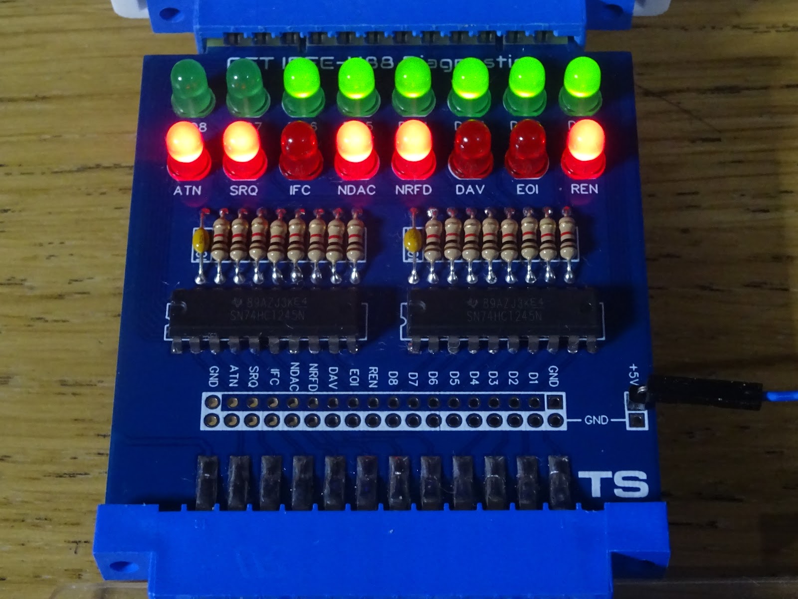
This board plugs into the IEEE-488 port and has 16 LEDs which light to show the state of the bus pins. The LEDs reflect the voltage level on the pins, so when everything is released and all lines float high, the LEDs will all be on. If any lines that are asserted, the LED for that line will be off.
When doing the POKE and PEEK tests above, if the LEDs change when you POKE the pins, then the output side is working, and the input drivers are at fault. If the LEDs do not change, then the output side is at fault.
You could make something like this to take power from the bus, but to limit loading on the bus, I have used buffers to minimise load on the bus, so the board needs 5V power, and for that I use the same datasette power pass through boards I used to use with the PET microSD disk drives.
There is a pass through for the IEEE-488 as well, so you can monitor activity during normal operation on the bus. Who doesn't like blinkenlights?
I have listed these on my Tindie store, as PCBs, kits or assembled units.
2023 Update
There is a new version of the PET IEEE-488 diagnostics.
http://blog.tynemouthsoftware.co.uk/2023/10/pet-ieee-488-diagnostics-updated-version.html