
This one is quite a rarity. It appears* to be a prototype of the less common variant of the Jupiter Ace.

The Jupiter Ace 4000 was the second version of the Jupiter Ace.
4000 makes it sound a lot more impressive than the plan Jupiter Ace. But 4000 of what? was it from two thousand and seventeen years in the future of 1983? did it have 4000 bytes of RAM? 4000 transistors? 4000 1K resistors, 4000 magic beans? Who knows, but it was still essentially the same machine with 8192 bytes of ROM and 1024 bytes of main RAM, 1024 bytes of video RAM and 1024 bytes of font RAM. That is a total of 3072 bytes of RAM, but that it would be really stretching things to round that up to 4000. So none of those give us 4000, not even in hexadecimal, not even in Welsh.
The main changes it seems were the addition of a composite video output jack labelled "Monitor", a transistor amplifier driving the speaker, and I think a stronger case (but I don't have an original Ace here to compare it to). Other than that, it was the same 3K machine as it's predecessor and the main benefit was I believe it was normally bundled with a 16K RAM pack.

The board inside this unit is not however the normal Jupiter Ace 4000 board. It came from some who used to work for Cantab, the company which produced the Jupiter Ace and Jupiter Ace 4000.
It looks like a more colourful version of one of my prototypes with various bodge wires and chips stacked up on other bits.

The board is labelled issue 1. Also included was an unpopulated issue 3 PCB - I believe issue 3 was the production board. There are a few oddities here, included a track that is broken, it could be that was intentional - the same track break has been scratched into the issue 1 board.

Looking at the modifications, it would appear they were trying to replace the two lots of 8x 1K resistors which usually separate the data bus from the video RAM and font RAM with 74LS245 bus transceivers. I can see that would be a neater solution than resistors, but the timing would be difficult to get right, and it certainly looks like they were having to make quite a few changes to the design to enable that.
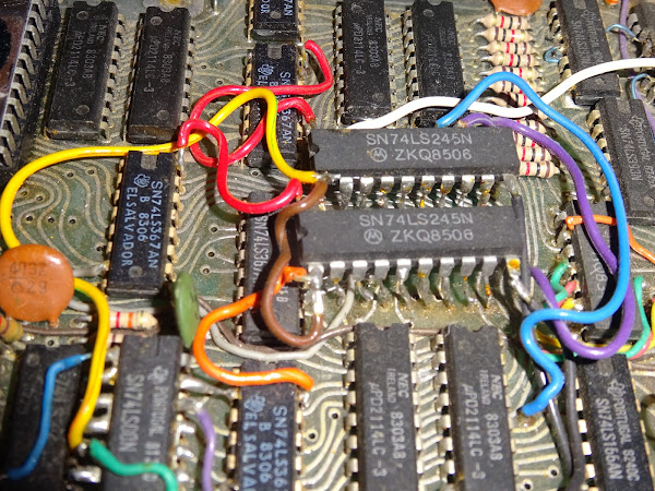
Rather oddly, there is a 40 pin socket on the bottom of the board, soldered to the pins of the Z80 socket on the other side.

There are a few bit missing, including the speaker (which may have fallen off in the last 40 years), and the 7805 regulator (which was probably removed deliberately). There are the remains of two wires soldered to pins on the edge connector, 0V and 5V, so presumably the board was being powered from a bench power supply rather than a 9V DC supply.

Looking around the modifications, everything appears to be intact, including the two custom Ace branded EPROMs (not bad for something with a relatively small production run).
However, there are two things wrong about the ROM chips.

- they are the wrong way around, ACE-B on the left, ACE-A on the right. - I pity the fool that arranges the chips in the order BA.
- the left hand ROM chip has two pins not in the socket. One is an address line (A11), and the other a data line (D3), so I can't think of any reason that would be done deliberately. Maybe someone removed these at some point and didn't notice when they put them back?

The IC socket is also installed with the notch at the bottom, pretty sure that is an assembly error, not a deliberate intention to reverse the chip.
Like the original Commodore PET, the video circuits on the Ace run independently of the Z80. Even with no Z80, no ROM and no RAM, they will still generate a picture, so I thought I would just try it as is first to see if there was any reason for the ROMs to be that way.
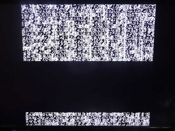
I did get a picture on the screen, but it was rolling. It looks like the vertical sync is missing - nothing to do with the ROMs, that's just another fault to fix. The screen contents were random pixels, indicating that the font RAM had not been written to. They were also different, indicating the video RAM had not been cleared.

I carefully removed the ROMs and read in their contents in the Stag P301, the only thing I had that supports 2532s (here shown with one of two 2532 replacements I burned to test later). They both read correctly as 2532 EPROMs (even though they have custom markings), and match archive ROM images of the two halves of the standard Jupiter ACE 8K ROM.

There is a mysterious green wire going under the ROM socket, but that appears to be repairing a broken trace. I double checked the enable pins, and they are still wired as the original Ace, where ACE-A goes in the left hand socket, mapped to 0000-0FFF, and ACE-B in the right hand socket is mapped 1000-1FFF. The red wire on the 138 from pin 16 to pin 6, puts VCC on one of the enable puts. This is the same as the original schematic, so it may have been modified and then reverted.

With the ROMs now in the correct sockets and with all the pins in place, I tried again.
No change.
I also tried the two replacement EPROMs, also no change.
I tried a new Z80, that also made no difference.
I tried various things at this point, but the Z80 did not seem to be running.
I then remembered the 40 pin socket below, and had an idea.

I made this rather odd contraption from an old RC2014 module PCB which has a socket for a Z80 wired directly to the bus. I fitted a pin header in that socket, and could then plug that into the 40 pin socket on the bottom of the Ace board.
All I needed was a suitable host, and for that I employed the services of a Minstrel 4th.

That allowed me to test two theories:
- The Z80 is running, but unable to write to the video RAM (or the video RAM is not working).
- The Z80 is not running, but the video circuitry is running correctly.
So, for the first test, I plugged the RC2014 card into a Minstrel 4th, and then the Ace 4000 board. The Z80, ROM, RAM and the 367 chip which reads the keyboard were removed from the Minstrel 4th, leaving just the video circuitry in place.
This should mean that if the Ace is running and it is a display problem, then the display on the 4th should work and would display the blank screen with a cursor on the bottom row.
It didn't.
All I got was random pixels again, different random pixels though, since it is just showing the uninitialised video RAM. There was no rolling this time as the output was from the Minstrel 4th.
So theory 1 is ruled out. Let's try theory 2. (Just a reminder of how much smaller the Minstrel 4th is.)

The idea was the Minstrel 4th had the Z80 and it's ROM and RAM, and the Ace board was just being used for the video RAM and video output. I tried various combinations here, Z80 in the 4th, ROM in the Ace, Z80 in the Ace, ROM in the 4th, Z80 and ROM in the 4th, and Z80, ROM and RAM in the 4th. The best I got appeared to show the video RAM had been cleared (or at least mostly set the the same value), but the character RAM remained unprogrammed. Something was stopping things working correctly.

I did have some success with a test ROM I found on a German Jupiter Ace forum. This wrote a font to the font ROM, then a test pattern to the video RAM, then beeped, cleared the screen and looped back to the start. On the 4th by itself, it worked correctly, but not when the Ace 4000 board was involved.

With the Ace also connected, the display was sort of there, but it was not correct, and it did not beep (the beeper was present on the 4th board, so was active on the Z80 bus).
I couldn't get anything running with the Z80 in the socket on the Ace, only the 4th. Those sockets should be wired in parallel at this point. It was clear some of the socket pins where dodgy. The original Z80 was also apparently desoldered so the pins were already a bit ropey.

This all took place over quite a while (my apologies to the owner who has been very patient and understanding). I have gone back to it a few times between other projects.
One of those projects was where I rather optimistically designed a 48K RAM module for the Ace, but was never able to get the board running to be able to test it (and I would have had to clean the edge connector and removed the solder blobs where the power wires were, so I would rather not).

It was designed to fit into the shell of the divMMC future / SD2PET, and has a power LED and reset switch. Just imagine the luxury
If there is any interest in a 48K RAM module, let me know. I don't currently have any way to test it, so it will probably just go into the "maybe one day" box.

(this is an artists impression, with an empty case as I didn't want to disturb the edge connector).
At this point, the following would need to be done to get further with the Jupiter Ace 4000 board
- Reinstate 7805 regulator and speaker
- Replace 40 pin Z80 socket, and remove lower socket
- Fix vertical sync circuitry
- Fix whatever is stopping it running if not resolved by the above
The the challenge would be finding what is blocking IO reads or writes and stopping both the Forth and the diagnostic ROMs running correctly.
And even then, there is the possibility that this was an abortive attempt to add the 245 buffers, since the issue 3 board went into production with the original resistor multiplexing. I can think of two reasons why they reverted to the resistors.
- it may have been cheaper to fit 16 resistors than two 74LS245s. In modern day pricing, that would be 16p versus £1.79, so it is quite possible
- it may be that it never worked correctly, and they didn't get the timing to work so went back to the old design.
So really, a lot of those mods may need to be undone to get back to the original board. But did it ever work? there is also much damage to pads and tracks, so that does not seem a viable option.
After much thought and going back to this a few times, I have to concluded these repairs should not be carried out. Speaking to the owner, they agreed and arranged a long term loan to the Computer Museum, which will probably be the best option for this board.
Coda
The case doesn't fit this board due to the rear mount 40 pin socket. I have looked at building a replica board to sit in the case, so the owner would end up with a usable Jupiter Ace.
I looked at various PCB designs on the internet, from Grant Searle's millimetre accurate replica of a standard Jupiter Ace PCB, to various modern versions that swap out some of the less available parts.
There was also the spare real Jupiter ACE 4000 PCB supplied with the other board, this time an issue 3. That has a bit of damage, and again it would seem wrong to try to populate it. Not at least as there is no silkscreen or any good photos of a populated board. The vias are the same size as the pads, so it is really difficult to see what it going on, and part placement and values with involve a degree of guesswork.

I am not convinced that any of the schematics on the net are correct. I know at least four people that have tried to build something according to those schematics, and only Grant's apparently resulted in a working machine. See my original post on the development of the Minstrel 4th to read about my attempts:

The more I thought about it, I didn't like the idea of going back to the original schematic anyway, due to it needing 2114 SRAM chips and 2532 EPROMs. The original design also lacks a back porch on the video signal. It's not as bad as the ZX80 and early ZX81s which also lack the back porth, as the Ace has a black video border rather than going straight to the white level as in the Sinclair machines.
I did have a mad idea of designing a Minstrel 4th to fit into the Ace case. I even did a board design for it, but I don't think I will get any of them made as the parts are too difficult to get hold of these days, and there aren't likely to be any spare Jupiter Ace cases kicking around the place. Has anyone done a 3D printed case? (edit - Yes they have. Thanks to David Boocock for the link)

*Footnote
Whilst preparing the photos for the original post I noticed something odd with the 74LS245 chips (other than they were hovering above where the resistors should be). Their date code is 8506.

8506 is the sixth week of 1985. That is two years after the Jupiter Ace 4000 was released, and a year after Cantab went out of business. The rest of the chips on the board are from early 1983 (or earlier), matching the date code of 8318 on the PCB.
So I don't think this is actually a prototype after all, but something someone did sometime after 1985? (well, it started as an early 1983 prototype, but the colourful 245 mods seem to be at least two years later).
That sort of makes sense of the fact the 7805 was cut off rather than never being fitted, and the Z80 being one desoldered from a board, maybe it was desoldered from this board, and then the two sockets were fitted and the rest of the mods made a few years after the company when down the pan?
Possibly an attempt to refine the design for a new release after Blodfield bought out Cantab? Or maybe someone tinkering in a shed using an old Jupiter Ace board as a Z80 SBC for something else, and later on it was reunited with the original ROMs (albeit with two bent pins and the wrong way around).
I am not sure we will ever find out.
Footnote #2
We found out.
After I posted this on Patreon, the current owner got in touch with the person they got the board from:
"Short form - mea culpa, the bent pins, extra chips and colourful re-wiring were all me. The board wasn't preserved as a museum piece, it was used it as a platform for experiments to learn about the Z80, Transputers and other interesting things. The bent pins and mis-aligned chips were a result of packing and unpacking things over several home moves from 1980's to 2010 and at one stage the chips were store separately from the boards."
So that confirms this Ace 4000 was repurposed as something else when it ceased to have any value as an Ace 4000.
That doesn't change things though, this is still probably going to be preserved in it's current state as a piece of modern art.
Footnote #3
This is possibly the only piece ever written about the Jupiter Ace or the Minstrel 4th that does not show the output of a vlist command.
Footnote #4
Despite the resounding clarity of decision from twitter, the board will be remaining as it. A prototype Jupiter Ace 4000 board with some later modifications. Preserved as is to confuse future generations.

Advert
This is an expanded and updated version of an earlier post on my Patreon, if you would like advance previews or insights into what goes on behind the scenes, you can follow along on there.
Advert #2
If you want to build you own Ace compatible computer, the Minstrel 4D is available in kit and built form from The Future was 8 bit.

Advert #3
If you would prefer to program in BASIC rather than Forth, there are full kits available from my Tindie store for the Minstrel 2 (ZX80 compatible) and the Minstrel 3 (ZX81 compatible).
