
I have been meaning to write up the history of the various versions of Mini PET, so here it is.

It all started a long time ago when I was working on some tools to help repair PET boards. I had built various boards to bypass the onboard ROM and RAM chips, and had been working on something to bypass the onboard display.

That board duplicated the onboard video RAM with some dual port RAM which was scanned by a microcontroller to display the screen on a small 240x320 LCD panel. This gave a 1:1 pixel perfect copy of the PETs 200x320 display, other than an extra 20 pixels top and bottom.

I ended that blog post (http://blog.tynemouthsoftware.co.uk/2016/08/pet-lcd.html) with the following:
One final thought, this is a 6502 CPU, ROM, RAM and a display. Stick in clock, reset and some IO, and you've got yourself an SBC. Add the appropriate ROMs and IO and you've got yourself a mini PET........


I was looking at using this for testing machines with faulty displays, and also added the option to drive PET monitors. The idea being that it could be used to add a 40 column display to an 80 column machine (but not to add 80 column to a 40 column machine at this stage)

It looks like I was borrowing the composite video mixer output stage of a Minstrel 3 for some reason


I eventually got that to the point where it was generating a clean stable display, and decided to see if I could actually make a Mini PET.

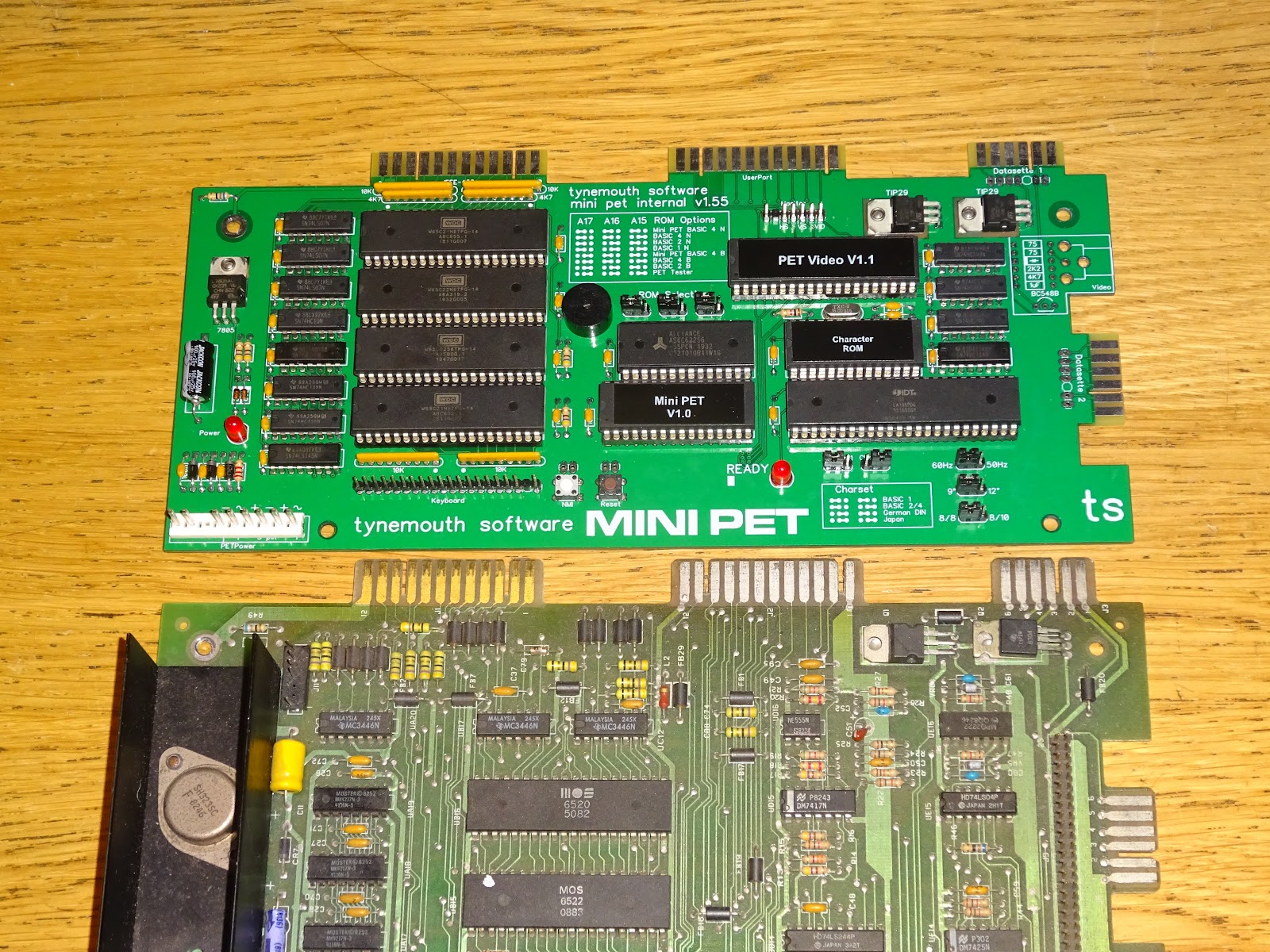
And here is Mini PET version 1.00.
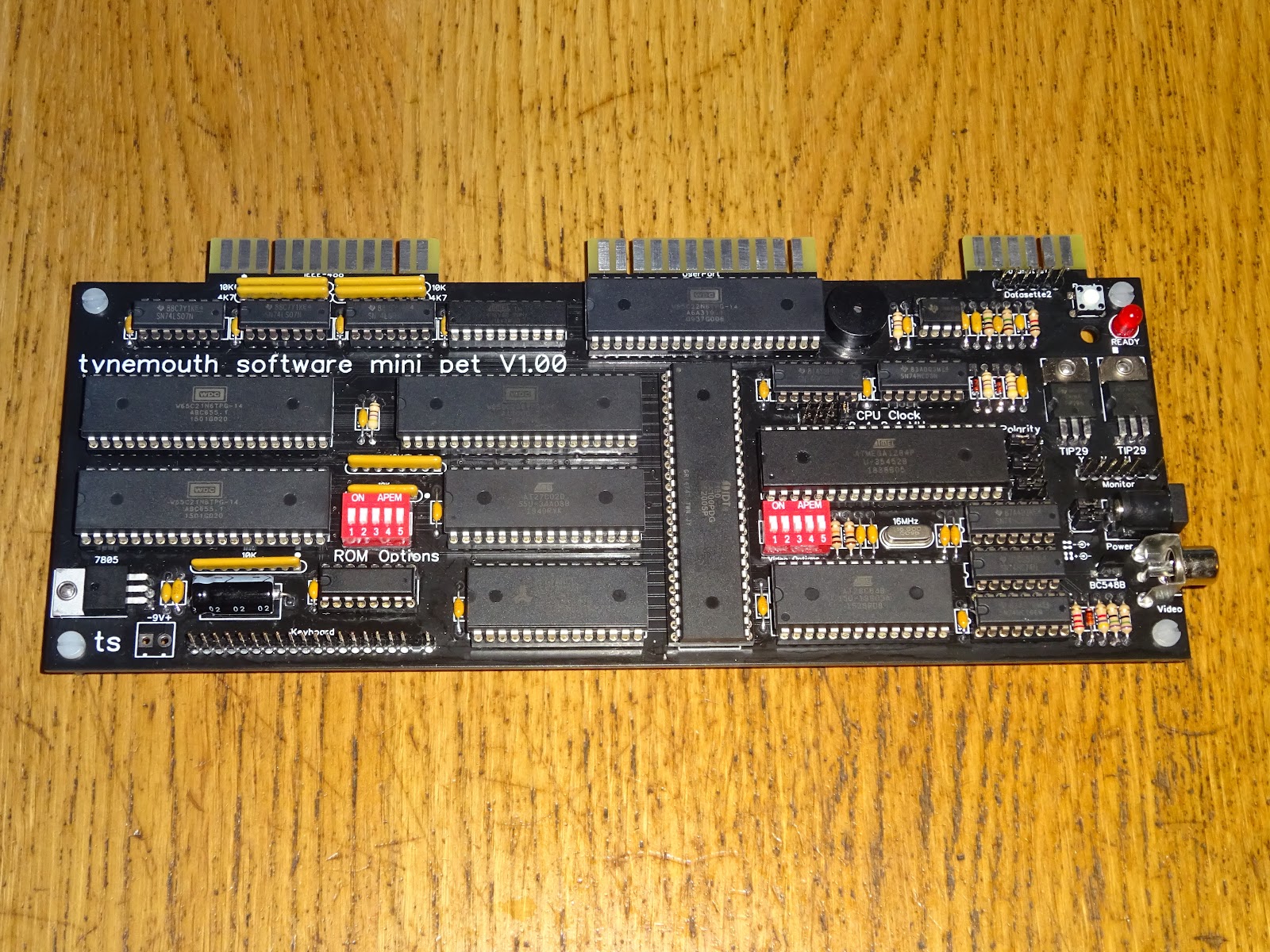
A key to this being possible is the W65C series of chips from WDC. These include versions of the 6502, 6520 and 6522 needed to make a PET entirely from new parts (which continues to be the case other than the dual port video RAM was has unfortunately now been discontinued)

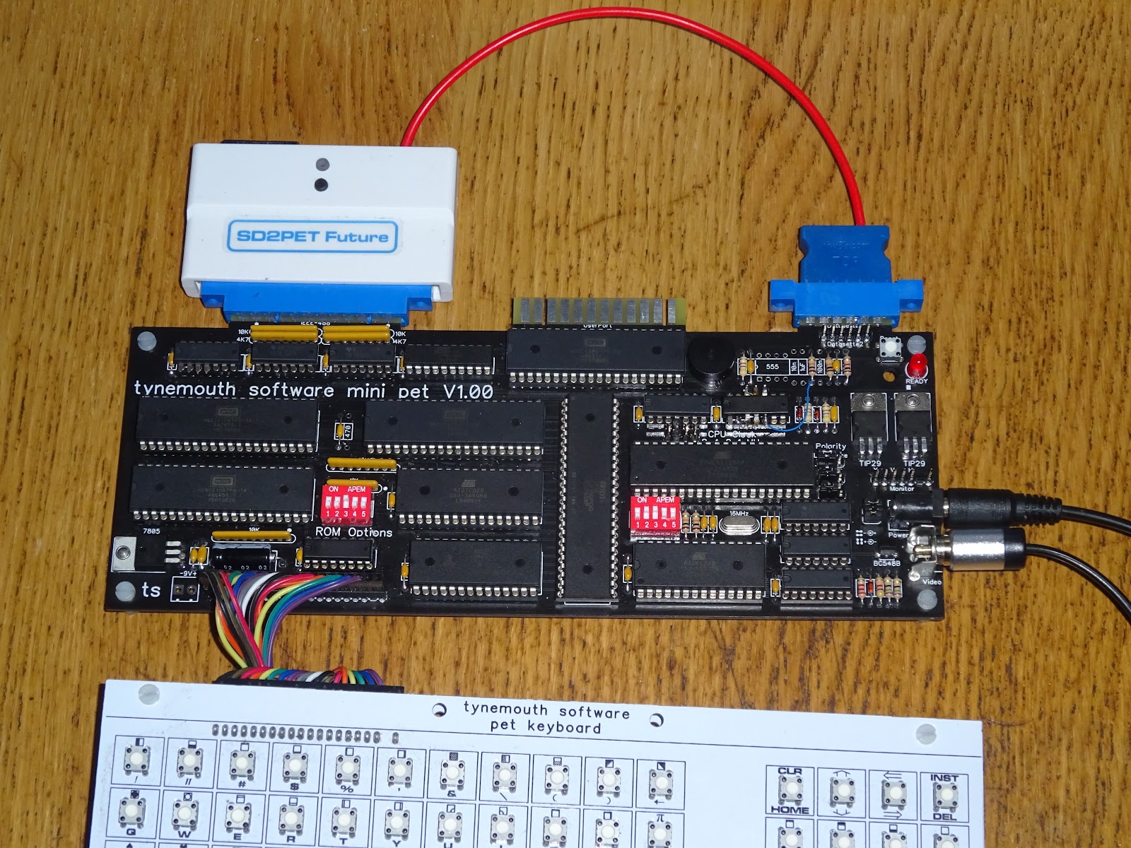
It needed a few tweaks here and there, but it wasn't long before it could play invaders.

It was all coming together quite nicely.
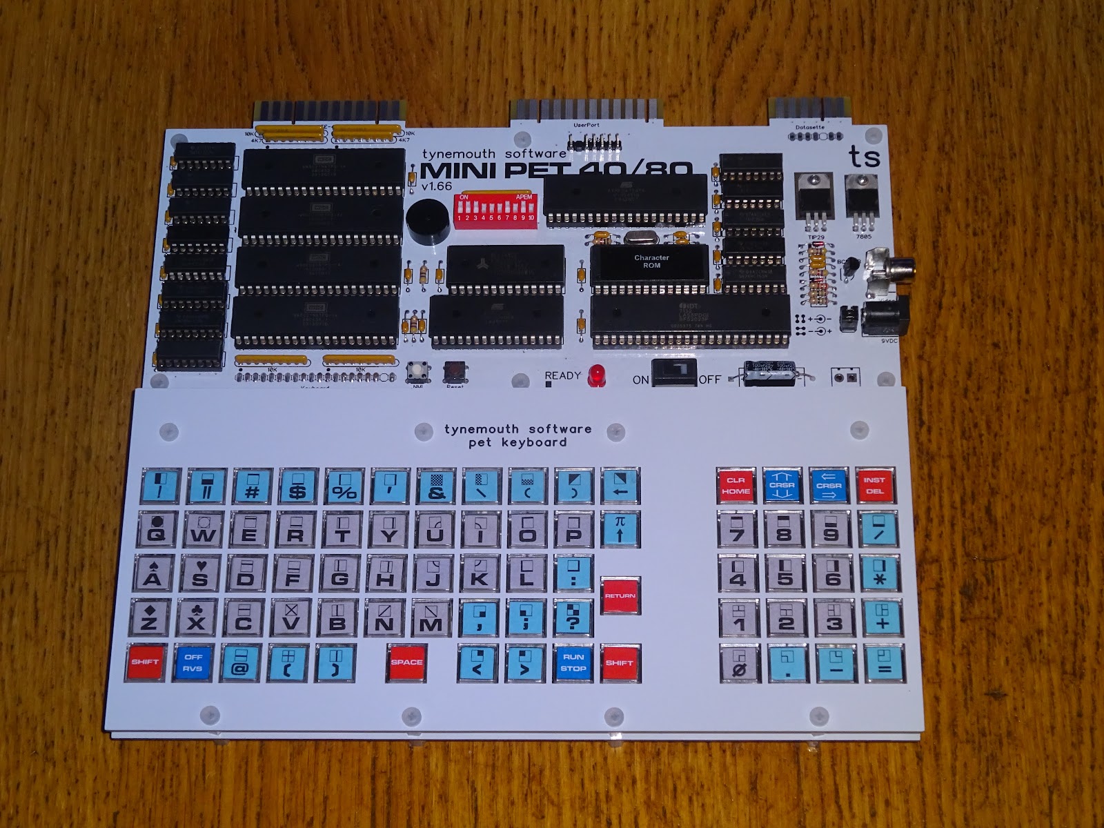
And with a few more tweaks, the first production board were ready.

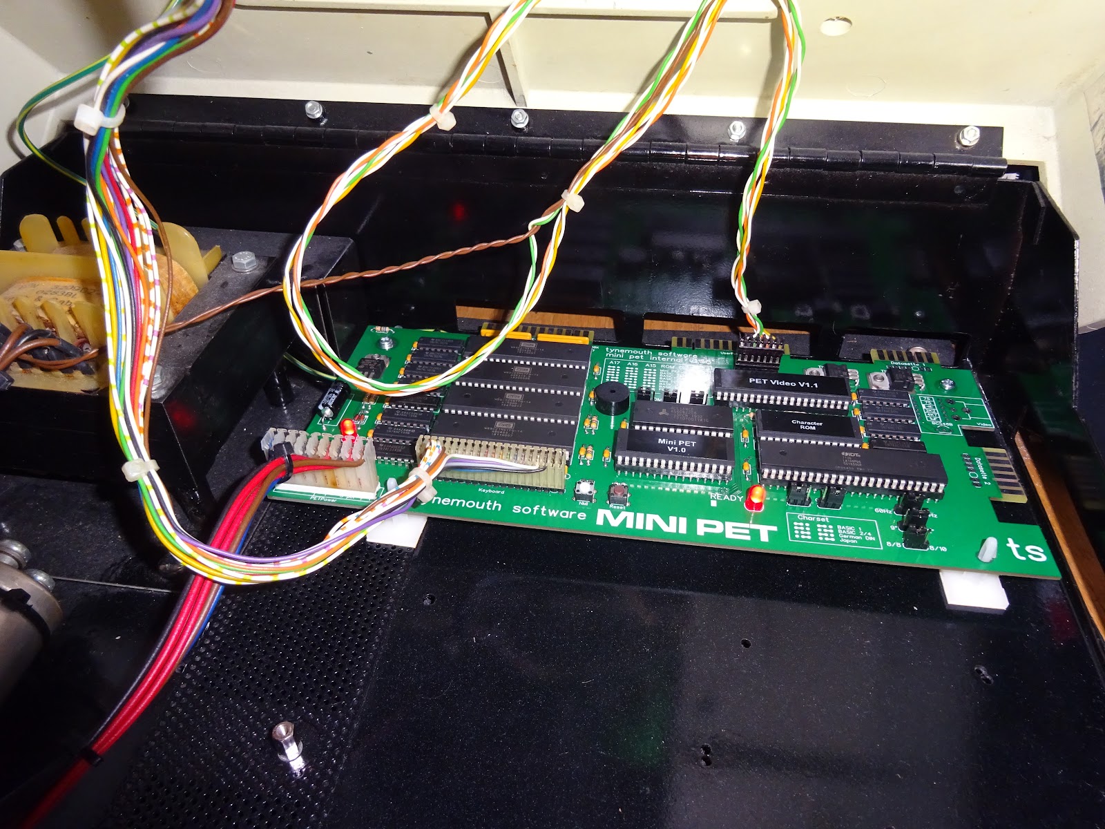
This board could either be used stand alone, or fitted into the case of a Commodore PET, with a separate board to generate 9V DC from the PETs internal power supply.

The three rear connectors lined up with original PET board edge connectors, but the board was only wide enough to pick up on one rear mounting screw.
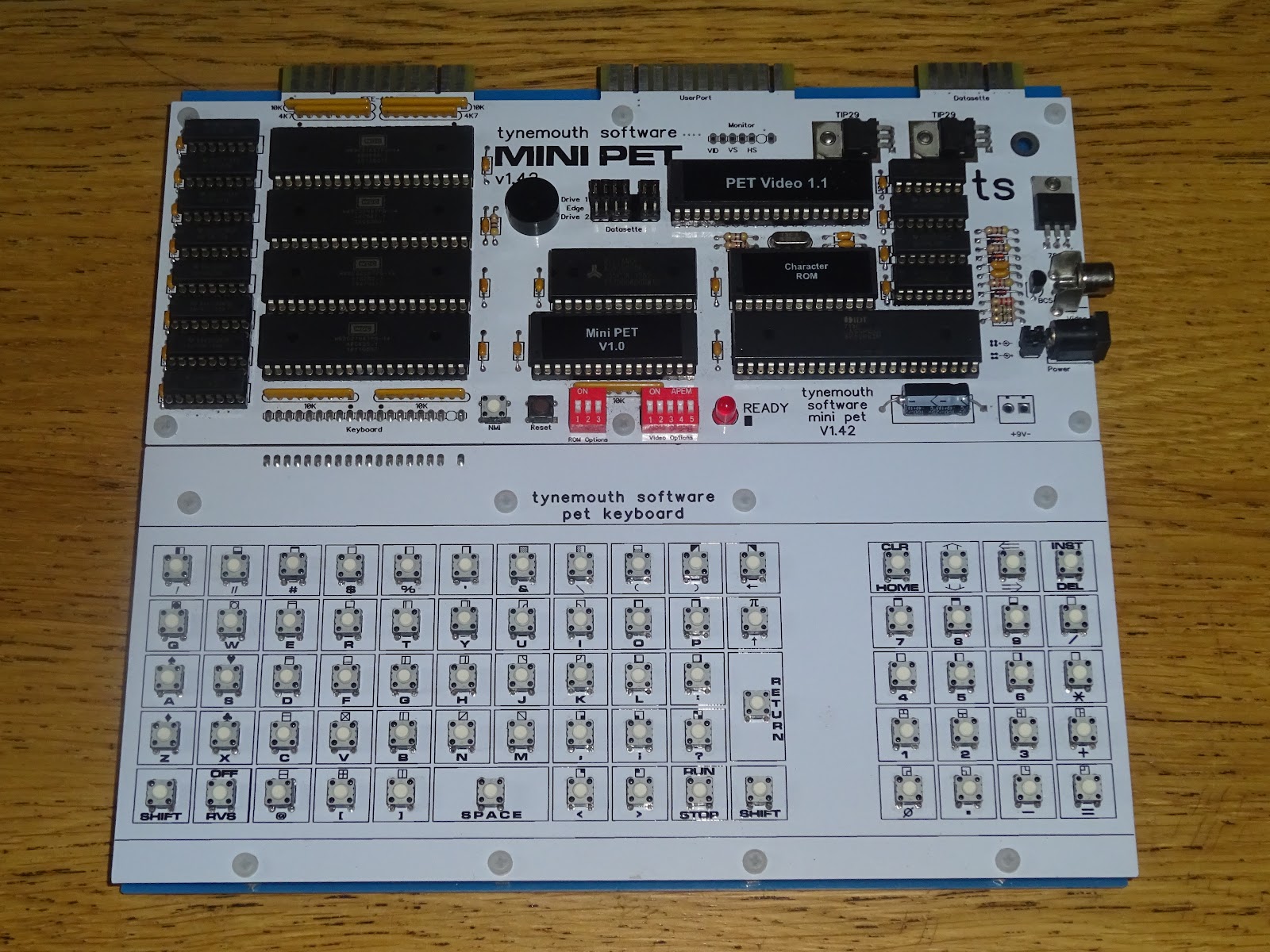
The size was set by the width of the PET replacement keyboard I had already designed, which itself was the same width as the PET chicklet keyboard.

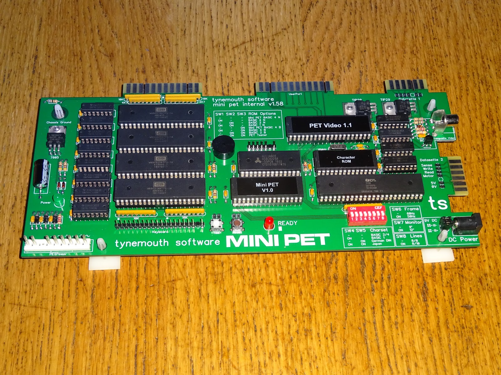
When ordering the second batch of boards, I got half white as before, and half with a green solder mask. That made it easier to differentiate between the stand alone (white) boards, and the PET replacement (green) versions of the kit. We had been using Mini PET "Kit A" for the stand alone kits and "Kit B" for the PET replacement ones, but the colours were easier.
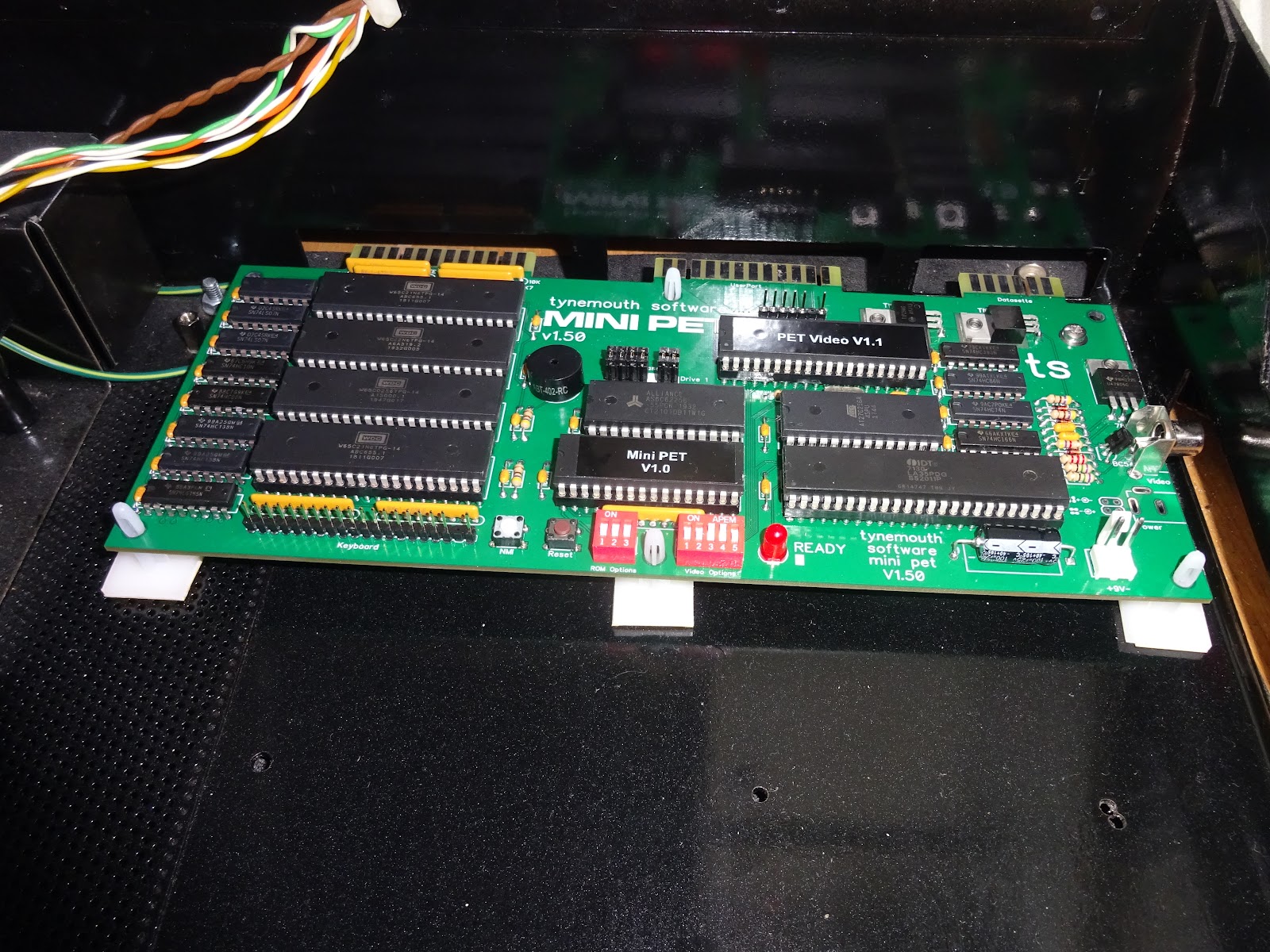
The first batch of green boards had been the same design as the white ones, but for the second batch of boards, I made some changes to better suit being fitted into the PET case.
The green board was widened to pick up the second rear screw hole, and the power board was integrated.

The central section with the chips in remained unchanged, just the sections around the sides were different. A second datasette port was added on the side to match later PET boards.
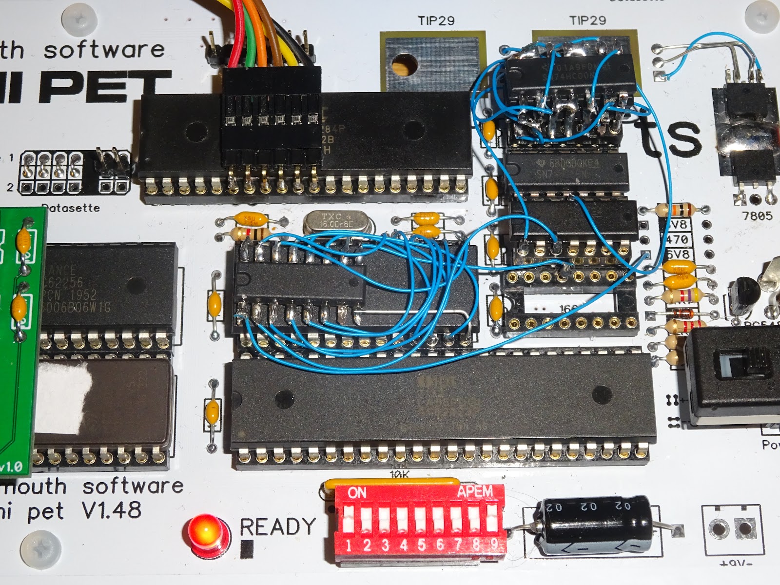
At one point, I updated the design of the internal board to use jumpers rather than DIP switches, but 1) if was more trouble to pack the kits with separate pin headers and jumpers, and 2) it was more trouble to solder them in. I went back to DIP switches for the full run.
The stand alone version also got some upgrades, including the deluxe keyboard version.

The next change was to add 80 column support. I had initially ruled that out as it required so much extra circuitry in the 80 column PETs. However, it turned out most of that was due to the video RAM they had available not being fast enough and having to alternate between odd and even banks to keep up. That also meant that switching to 40 column mode involved a significant amount of rewiring.

The first version of the 40/80 was the same format as the previous models.
At the same time (end of 2020 / early 2021), there was also an internal through hole kit version of the 40/80.

At this point, I had shut down my Tindie store and was very much reliant on TFW8b to sell these kits, but they still had stocks of the standard Mini PET kits, so these versions were never sold. They did however express an interest in a pre-assembled version of that board, so I designed one.

The WDC 65xx chips were available in PLCC, as was the IDT 7132 dual port video RAM chip, so I went with those. I left the two ROM chips as through hole to simplify things during production.

Since there was space on the board, I wondered if I could fit an SD2PET on there as well, hence the name, the Mini PET 40/80D, in the same style as the PET 80296D and Commodore 128D, both of which had built in disk drives.

TFW8b didn't like the location of the SD card slot, so it was moved to the side where the second datasette port had been. I wasn't sure if that would work, it meant either running the SD card SPI bus from one side of the board to the other, or running the IEEE-488 bus from top left to button right. Neither was ideal, but the SPI bus and other SD card signals required fewer wires, so I went with that and it worked out fine.

That was put on hold a few times due to economics, chip shortages etc. The stand alone 40/80 was also progressing, waiting for an opportunity to make kits again. In that time, I worked on the ROMs, adding a built in file browser and expanding the built in self test.

We talked about various options, and a new improved Mini PET 40/80 spec was conceived, with soft power on, 9 way D monitor connector, both datasette powers, 40/80 switch, dedicated NMI button to launch the new file browser etc.

My first attempt added the extra buttons above the numeric keypad, but I was not happy with this as it spaced the buttons out a little too much.

For the final board, I went back to the spacing of the original deluxe keyboard, and added the new switches to the side instead.

It was at this point that the PCB manufacturers messed up with a batch of boards and so the Mini PET 40/80 Stealth edition was born.


The Mini PET 40/80 was launched with some arty shots from The Future Was 8 bit.
That seemed to be well received, so the 40/80D was back on the cards. Another spin of the board followed, as I wanted to add back the second datasette port (although after the fun I had with the fast loaders on port 2, maybe I shouldn't have bothered).
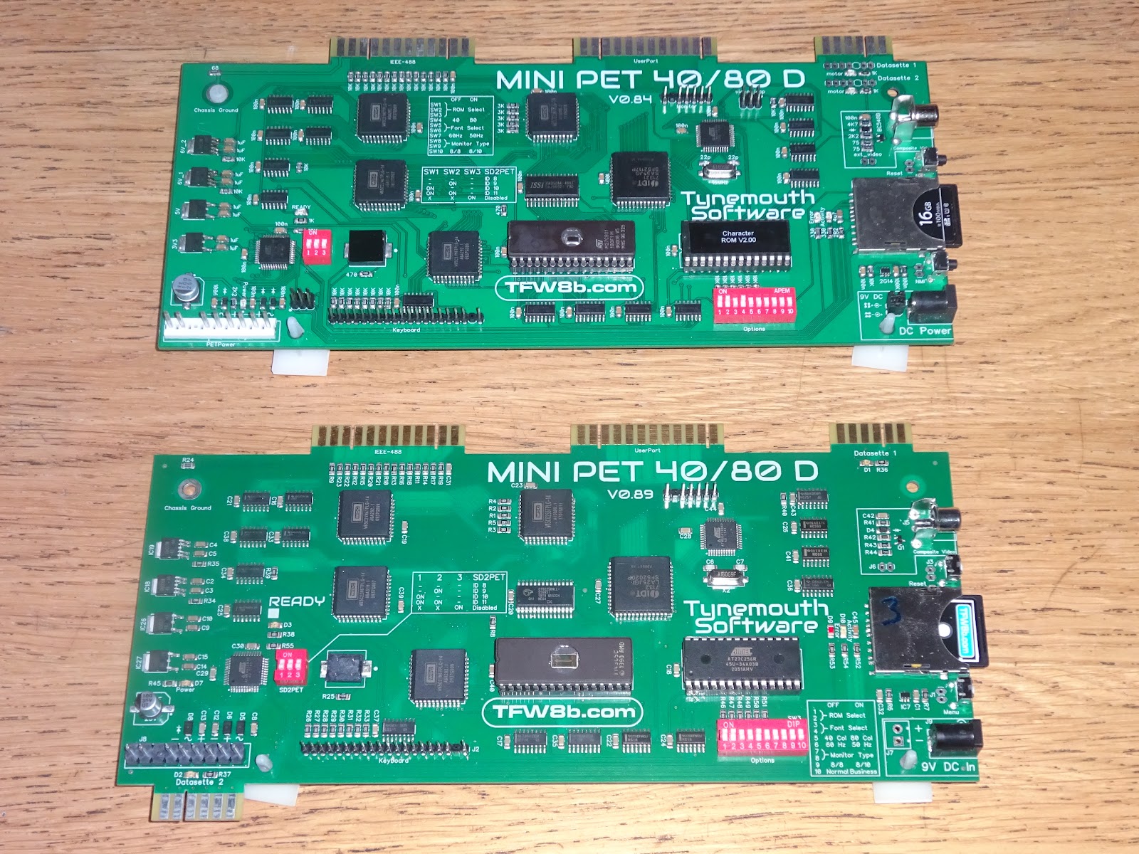
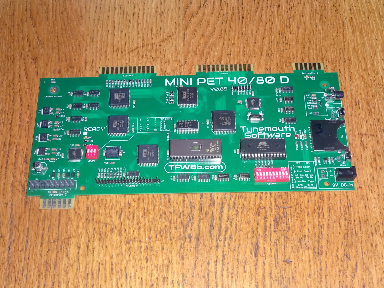
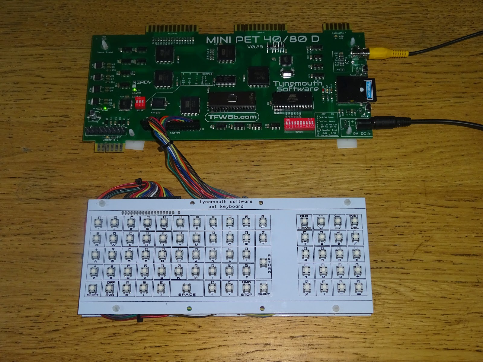
The final change was adding the second datasette port on the bottom edge.

This board is different to all the others shown before. This one is factory assembled, the first of a trial batch. Just to the left of the power connector you can see the first fiducial I ever put on a PCB. It looks rather nice coming out of the factory as a complete unit, just needing the micrcontrollers programmed and the ROM chips installed.
As with the previous "B" kits, the "D" board is designed to fit into a PET case. I usually test with the extremes of the range, starting with an original 2001 with the 9" monitor and built in datasette.
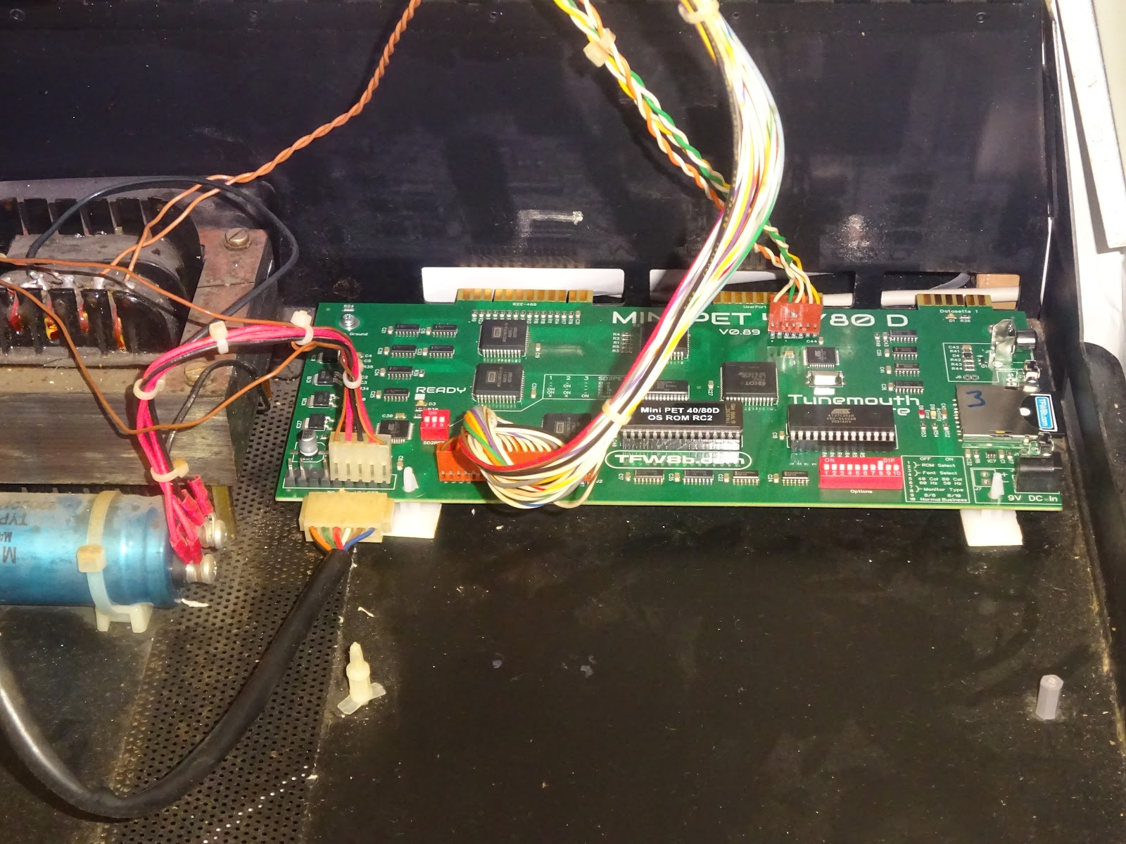
The 2001s have the 5 pin version of the power supply connector. The board is designed to accept either this or the 9 pin version used in other PETs. The prototype run of factory boards had black power connectors where the pins were a bit too short, you can see that 5 pin connector is just hanging on, the production run have the correct taller white connectors I had originally specified.

The internal datasette drive on the 2001 is plugged into port 2. So you can still load from tape if you want to.

At the other end of the range, here is the board fitted into one of the later CBM models with the 12" monitor. (everything apart from the 8032-SK and 8096-SK, the keyboard and power supply cables doesn't reach, so it would require a bit of fiddling - consider then as not supported).

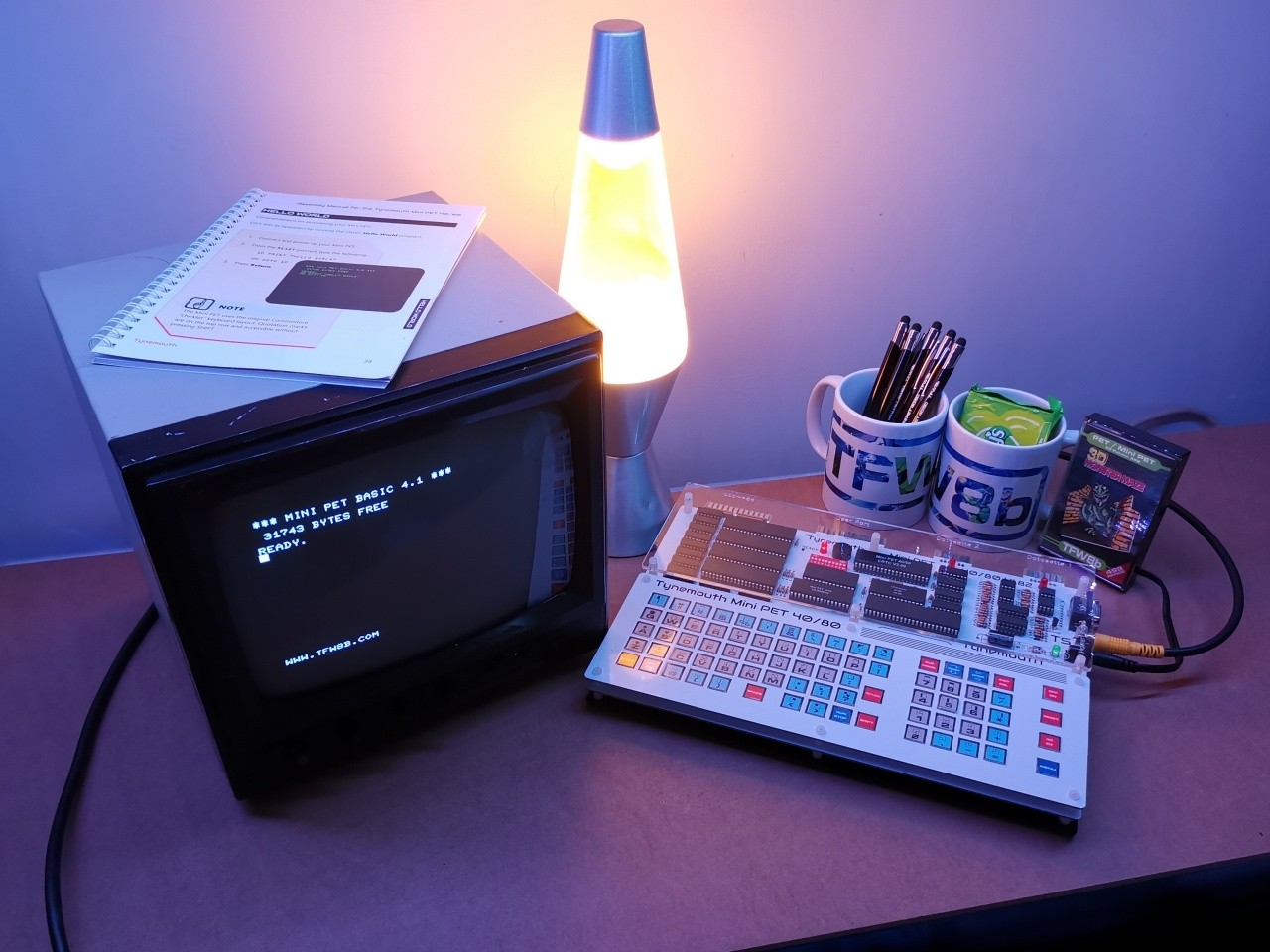
There are a number of ROM versions available, by default it boots to Mini PET BASIC 4.1 and 32K of RAM.

As before these can drive a PET with a 9" or 12" monitor with 40 or 80 columns.
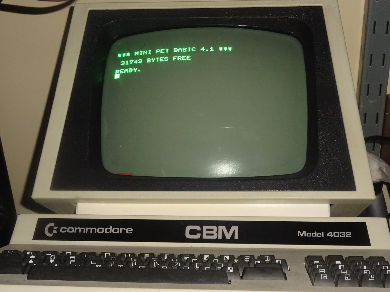
You can go 80 column even if the PET was originally only 40 column


There are connectors on the right for 9V DC power and composite video out, which can be used for testing.
You can use a normal / graphics keyboard, or the business keyboard (with the smaller numeric keypad and numbers on the top row of keys). Real PET ones, or replacements such as the ones I used to make, or the Cherry MX switch versions from 8-bit Guy's mate (https://texelec.com/product/petskey/) or these from Steve Gray (http://www.6502.org/users/sjgray/projects/mxkeyboards/index.html).

Although you can do that, the Mini PET 40/80 with the built in keyboard is a better option for bench use.

So there is the potted history of the Mini PET, Mini PET 40/80 and Mini PET 40/80D. If you fancy one of your own, the latest incarnations are available from The Future Was 8 bit here:
https://www.thefuturewas8bit.com/shop/tynemouth-products.html

PCB only and PCB + programmed parts only versions of the earlier boards and separate keyboards are available from my SellMyRetro store (UK only - sorry).
https://www.sellmyretro.com/store/tynemouth-software
This post is an expanded and updated version of several posts from my Patreon. If you want advance previews of posts like this and behind the scenes progress on new projects, you can follow along and support me on Patreon:
