
I had a request for help with a broken VIC20 from a friend in America. Seemed like a normal faulty VIC20 until he sent me a photo of the board.

Well now, that's not your average VIC20. That's a very early one with the same board* as the VIC-1001, the original Japanese version.
* well, almost the same, see next week's post for more information on the differences
Compare that to the usual 2 pin VIC20 board and you will see it is very different.
I like the VIC-1001 layout better, it seems a lot cleaner. I Presume the board was reworked by Commodore USA for FCC compliance reasons, see all the filtering added to the power input on the right, and the tin can for the VIC and the clock circuitry.
All the interesting stuff seems to be on the left hand side of the board.

The layout of the CPU, ROMs and IO chips in a row is reminiscent of the C64.

The right hand side is just the cartridge and side connectors, and the massive heatsinks for the 5V regulator and bridge rectifier. (the board uses about 1.5A in normal operation so it does get a bit warm).

The back of the board on the left is just as sparse, lovely track work though.

It is almost as if it was originally only going to be half as wide, maybe with the cartridge slot rotated 90 degrees and joystick port on the side. Not quite small enough for this mockup photo with a PET chicklet keyboard, but not far off.

This one was inside a normal breadbin case. An early one with a silver VIC20 label and a keyboard with PET style keycaps.

VIC20s of this era had a dangerously misleading sticker on the bottom.

Seems to imply it takes 117V AC directly in the side, not 9V AC via the AC transformer. Made worse by the 2 pin power connector being similar to that used for electric shavers at the time.

I hope no VIC20s got fried due to that.
The US 2 pin connector is different to that used on UK 2 pin VIC20s (even though both are 9VAC). I don't have one of those, so crocodile clips to the rescue.

Time to power it up.
What's wrong with it?
Well, it is showing a screen full of garbage characters and colours.

OK, not a bad start. The VIC chip is probably working, as is the 6502 and some of the RAM and ROM.
It is not like a PET where you will still get a screen of garbage if you remove all the system ROM and RAM and even the CPU.
Here it has got as far as initialising the VIC chip, but not as far as clearing the screen or putting up a READY prompt. Could be a bad BASIC ROM?

I am told the VIC has already been replaced, and probably several of the other chips as they are all showing 1982 date code, whereas the rest of the board (and the KERNAL ROM) are showing 1981. Matching the nice "Produced 7/81 sticker" on the heatsink.

The KERNAL ROM and several of the other 1981 chips have an unusual sticker on them.

I am told "保" means "Save" or "Protect". Not sure what that means in this context. The KERNAL ROM chip contents is binary identical to the normal NTSC VIC 20 KERNAL ROM.
I did try them out of a good VIC20 board, and they were all fine.

Time to get the Penultimate Cartridge out and fire up Dead Test.

If you hold down the reset button (on the right of the cartridge) at power on, it will jump straight into Dead Test. The design of the VIC20 means that the KERNAL ROM and the RAM at $0100-$01FF need to be at least partially working. If it does not start, check those.

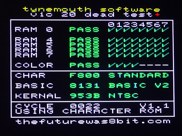
It did start, so that's a good sign, and the ROMs all pass.
However, it seems to consistently show RAM faults in RAM 5, 6 and 7. It seems unlikely that all of that RAM would be bad, something like that would normally be an issue with address decoding / chip select lines, with those chips not being enabled when they should be, or something else being enabled at the same time and causing bus conflicts. The 74LS133 and particularly the 74LS138s are good at failing and causing that.
The bad section covers $1400 - $1FFF, six out of the ten 2114 RAM chips (eleven if you count the colour RAM).

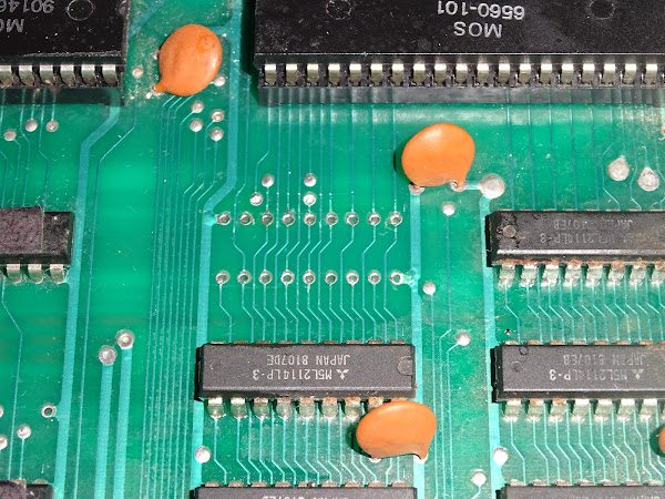
That is the top six here. They do look a little crusty. Not sure what's happened there.

Oooh, nasty. Never seen a head gasket failure on a RAM chip before. These are Mitsubishi chips. I could understand if they were made by Rover ......
It is just as nasty on the scope.

It is never good to see signals that are not high or low, but somewhere in between.
This board follows a grid layout, like the PET and many others of the era.

Letters go across the board, numbers up the side. You can see some of them circled above. The RAM chips are UA2, UA3, up to UA6 and UB2 to UB6. The colour RAM is on it's own over at UD3, and there is a clear gap at UC5. I wonder if there was originally another 245 buffer in that location?
When they moved to later boards, they kept those designations, even though they didn't use the grid any more. And when they added new chips, they numbered them.

The RAM on the VIC20-CR still has UD2 and UE2 and UE1, but the new 6116 2Kx8 RAM chips are U14 and U15 (as I am reading this back, I realise these designators refer to the grid on the normal 2 pin VIC20, but you get the idea anyway)
I have traced back those signals to the 74LS138 at UC1 and the 74LS245 at UD3.

UC1 is used to generate eight chip select lines for eight 1K blocks in bank 0. $0000-$03FF, $0400-$07FF etc. up to $1C00-$1FFF.
Five of these feed pairs of 1K x 4bit SRAM chips, giving the 5K of internal RAM. Three of them go to the cartridge connector where the 3K expansion can be fitted to fill the gap at $0400-$0FFF.
Several of those chip select lines were showing this intermediate logic state, so bad 138?
Well yes, possibly, but also the inputs were doing similarly odd things.

I replaced the 245 at UD3 and that fixed the signals going into the 74LS138, but there were still issues with the chip select lines coming out of the 74LS138.
I replaced that, and it fixed the signal coming out of the chip.
Great, sorted?
Well, no, there were still RAM faults. The same RAM faults.
Six bad RAM chips.
Six bad RAM chips? Surely not.
I decided I needed to be sure, so I moved the 74LS138 to a breadboard.

Most of the pins were wired straight through, but I moved the five chips select inputs and the five chip select outputs to the left hand side.
From there I could swap them around.
I found wherever I put the bad RAM, it failed, and wherever I put the good RAM it passed.

Here you cannot see the results as the bad RAM is at $1000, and that is used for the screen. You can however see the red and green marks in the colour RAM that confirm the good RAM is working in positions 6 and 7.

Six bad RAM chips.
I was a little reluctant to desolder and replace the six bad 2114 RAM chips.
The board seems quite fragile. I unfortunately damaged one trace removing the 74LS138. I am very sorry about that, and disappointed in myself. I managed to reattach the trace under the IC socket, so no harm done, but I wish I had not done that.
Traces on the top of the board are always tricky and almost all the RAM signals are on the top side of the board.

I cannot use a ROM/RAM board here because that only provides replacement ROM and RAM to the CPU, and the base 5K RAM needs to be visible to the VIC and the CPU (and also it would probably not fit in the case)
I did work out an alternative RAM replacement board that would plug into the character ROM socket with a single 62256 RAM chip to replace all 10x 2114 RAM chips in the base RAM. It would need a wire to connect it to another board in the 138 socket, and another to pick up R/W somewhere. The existing RAM chips seem to behave when disabled, so the modern RAM chip would do everything but the colour RAM (which seems to be fine).
Whilst I was pondering that, Bill sent me something else to be repaired, and also six 2114 RAM chips.
RAM Replacement
OK, here we go.
It took me about two hours to remove that. I really struggled to get all the pins free at the same time, and in the end, I decided to do something I do not like to do, but it seemed the best option in this case.
I had proved as far as I could that the RAM chip was bad, and I really did not want to damage the board.
So I cut off the legs of the chip.
It felt really bad.
But, it finally allowed me to get all the legs out cleanly.

One socket fitted. One new RAM chip. Fingers crossed.

Well, would you look at that. It was a bad RAM chip. It is 1K by 4 bits, so it only fixed those 4 bits. The other four are in the chip next to it.
Oh well. Those of a nervous disposition, look away now.

In for a penny, in for a pound.

Don't look, it's awful.
Cutting the legs off is really only a last resort. I would have liked the save the originals, even if it is just to retest them to prove they are bad. The chances of damaging the board were high, and the likelihood the chips were bad was equally high, so this seemed the safest option. In this case preserving the board was far more valuable than the saving the ICs.
All the bad RAM removed with no track damage, which was quite a relief. Working with single legs at a time holding them with tweezers and heating with an iron the legs were easy enough to remove. But it took many passes with lots of flux and desolder braid and resorting to the desoldering gun and even resoldering some of the pads to try to make the solder flow. Not a pleasant job, but easier than trying to remove the ICs whole.

Five more sockets fitted.

And then six of Bills 2114 chips. Not all matching, but all tested and working.

They are in sockets, so they could swapped if better matched ones are found in future.
That is assuming it works.....
Phew, was I glad to see that.
Testing
I left that running for a while, no problems were found.
I also used the Penultimate Cartridge self test for the soak testing. Again, all was working fine.

I went through quite a few games and everything seems to be fixed now.

The ROM chips are running a bit warm, as they tend to in VIC20s. Probably worth fitting some EPROM replacements and preserving the originals whilst they are still working.

The VIC itself is not that warm, so no need for a heatsink at this point, but it wouldn't hurt to fit one if you wanted.
Further Testing
I switched to using a Penultimate +3 to do the next round of testing.

That allowed me to test the IEC bus.

No problems loading from disk.

One of the oldest VIC20s playing one of the newest VIC20 games.

And just because I could, one of the oldest VIC20s next to one of the newest VIC20s.

All tested and ready to go back.
Important note on International Shipping
Shipping to the EU is once again going to be a problem, this time due to new GPSR regulations which appear to require considerable paperwork for every product I sell, in the language of any country I want to sell to, and with a named representative located in each of those countries. That is way beyound the means of my one man business. Like many others in my position, I am not going to be able to comply with the requirements and do not want to incur the fines for failing to do so.
It seems legislation designed to stop cheap and potentially dangerous imports from the far east is also going to kill off cottage industries and small makers selling on Tindie, ebay and Etsy etc. Hopefully they will sort this out and add a waiver based on product value or business size, and I will be able to ship again.
Oh, and it looks like America is likely to be adding import duties from some time next year, so get prepared for massive price increases and massive delays to orders as they put systems in place.
In the next few days, I will be setting I have set the store to UK only, I hope to open it back up to the US and the rest of the world early next year, and we will see what happens with the EU.
Advertisements
The Penultimate +3 with a built in SD2IEC drive is available from TFW8b.

Minstrel 2 and 3 kits and many of my PET repair and upgrade products are available from my Tindie store.
I will slowly be moving things over there from my SellMyRetro store, so if there is anything that you want, let me know and I'll add it.

More info can be found here:
- http://blog.tynemouthsoftware.co.uk/2023/09/minstrel-and-mini-pet-kit-updates.html
- http://blog.tynemouthsoftware.co.uk/2024/06/repair-parts-for-commodore-pets.html
Bluesky
For those interested in such things, I can now be found on Bluesky, and I expect to be posting more there.
Patreon
You can support me via Patreon, and get access to advance previews of posts like this and behind the scenes updates. If you want to see part two of this post, that is up on Patreon already. Also includes access to my Patreon only Discord server for even more regular updates.


