This is an old post, preserved for reference.
The products and services mentioned within are no longer available.
This week, an Oric Atmos was sent it. Couldn't find anything wrong with it. Sent it back.
There you are, nice short blog post. Thank you and good night.
Oh, you want more? OK. Well, here follows a comparison between the Oric Atmos and it's predecessor, the Oric-1, including a couple of repairs that didn't justify a writeup themselves.
When looking at photographs separately, I always thought the Oric Atmos was a larger, more substantial machine. I knew that it used the same board as the Oric-1, but I had thought it was along the lines of the Spectrum and Spectrum+, where the later machine is quite a bit larger than the original. When an Oric Atmos arrived on my desk, the back moulding looked very familiar.
It appeared to be the same as the Oric-1, only a tasteful orange colour rather than beige. I dug out an Oric-1 for comparison, and indeed they are the same size.
The front is different though. The Atmos has larger, nicer looking keys, although side by side, the Oric-1 was actually nicer to type on. Hands down looses to the Atmos on looks though. If you are going to call your company Tangerine, why not go for it!
Inside you would be hard pushed to spot the difference, both are issue 4 Oric-1 boards, one mid 1983, one late 1983.
With the boards removed, the keyboards beneath look different, but use the same connector. The Atmos has one extra key (FCTN) sitting at an unused position in the keyboard matrix.
Looking a the boards, the main difference is the Oric-1 has ORIC BASIC V1.0 ROM.
The Oric Atmos has ORIC BASIC V1.1 ROM.
The only other noticeable difference is the inverter chip which forms the main oscillator is socketed on the Atmos board, and a 74F04 is fitted.
This looks factory, so maybe they were in the process of changing that from the 74LS04 on the slightly earlier board.
The first of these repairs turned out to be quite straightforward. The problem was it was giving an intermittent picture via the RF output. When I tried it, I found the modulator was wiggling up and down quite a bit
Looking at the board, it was clear the solder around the two mounting posts had cracked and was making intermittent contact. A bit of flux and fresh solder and we're back in service.
The second repair was a little more complicated. This one wasn't booting. That can be many things, the CPU hasn't made it as far as clearing the screen and putting up the ready prompt. It could be the RAM, if there is no stack or zero page, the CPU couldn't complete the boot process. There are eight 64Kx1 chips, although only 48K is used as the top 16K is used for the ROM and there is no paging mechanism.
It could be the ROM, if no instructions or faulty instructions are read, the CPU won't know what to do. This was an earlier board with dual 8K EPROMs rather than the later 16K mask ROMs seen above. The EPROMs were socketed, so I took those off and verified their contents, and they were fine.
Or it could be the CPU was bad, or badly fed. I normally start by checking power, clock and reset. Power was there, and even though the Oric has a pretty poor reset circuit (see a
previous repair where I fit a 'better' one), there was a brief reset pulse. The clock appeared to be running, although it looked a bit rough. I traced it back to the 74LS04 which formed the main 12MHz oscillator, and as soon as I touched the pin with the oscilloscope probe, it came to life and I got a ready screen.
I had seen this same thing happen before on a
Harlequin ZX Spectrum clone. I power cycled it and again got nothing, probed pin 13 on the chip and it booted. Rather than a 74LS04, I replaced it with a 74HCT04, as I had found those were good for use in oscillators when I tested various chips for my
CPU / Clock / Reset board for the RC2014.
With that replaced, it is now working fine. I wonder if there had been similar problems in the field in 1983 which had caused them to change the chip to a 74F04 seen on the Atmos board?
I installed a diagnostics ROM and gave the machine a bit of a run through and it passed with flying colours. All eight of them.
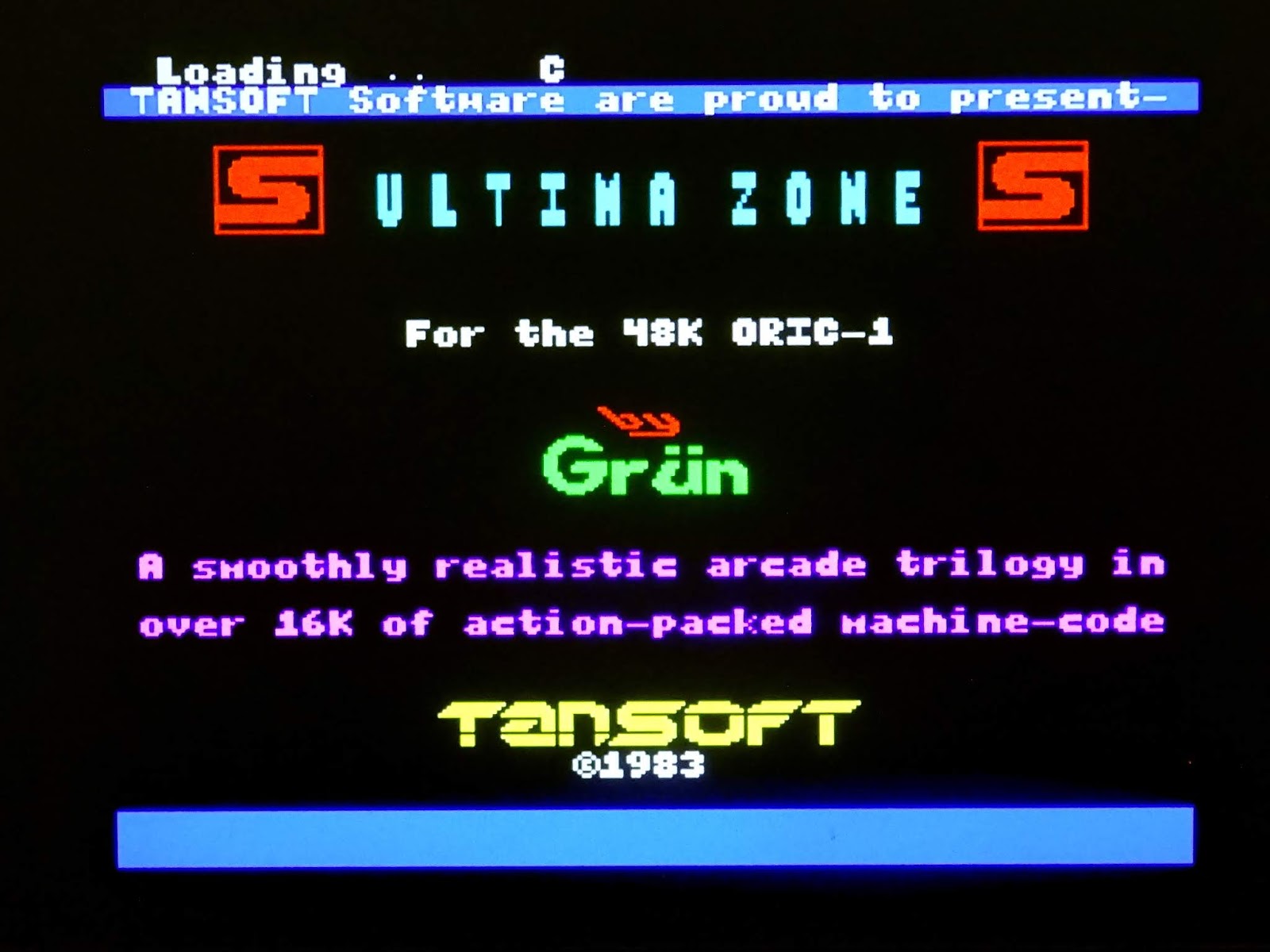
All that was left was to load up a selection of games and do a bit of testing.
Oh, and the Atmos, well, I suggested a
Retro Computer Shack SCART cable, as I think the problem was down to them being unable to tune into the RF on whatever modern TV set they were using.
(note the neatly labelled connectors on those leads, would have helped if the owner of the
Amstrad CPC 6128 from last week had got one of them instead)