There is a new kit on the block.
Introducing the Minstrel 4D. Shipping now from The Future Was 8 bit -
https://tfw8b.com/product/minstrel-4d-turbo-jupiter-ace-compatible-computer-kit/

This is a much updated version of the Minstrel 4th. It has many added features, whilst still retaining compatibility with the Jupiter Ace.

The main specs remain the same as the Minstrel 4th.
- Z80 CPU at 3.25MHz or 6.5MHz
- 49K RAM (maximum supported)
- 8K ROM (up to 15K ROM supported) (configurable 1 of 4 ROM images)
- 32x24 monochrome display with 128 user definable characters (+128 inverse)
- Microcontrolled based CRTC
- PAL or NTSC composite video output
- 1 bit mono sounder
- Expandable via RC2014 bus
- Forth in ROM
- Jupiter Ace compatible
It is quite a bit larger than the 4th, to be able to fit in all the new stuff.

RC2014 Bus
There is now space for four RC2014 bus connectors ("Minstrel 4D is designed for RC2014").

Most RC2014 cards should work, other that those with ROM or RAM or a Z80, since those are already present on the bus. I/O addresses 0x01 and 0xFE are used by onboard devices, the others are free for expansion cards.

You can mount the fourth slot horizontally, to give better access to one of your cards, or you could even add a backplane if you want even more slots.

Keyboard
The most noticeable change is the keyboard. This is using the same 12x12 mm soft touch tactile switches as the Mini PET 40/80.

The Minstrel 4D keyboard has the original 40 keys, with symbol shift, space and enter offset to the right by one, and an extra delete key (to save you pressing shift+0 all the time).
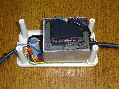
On the end are four new buttons. One is a soft power on/off (as on the Mini PET 40/80). Power is from 9V DC (centre negative like the Minstrels, Mini PET, ZX Spectrum, Commodore 16 etc.). A heatsink is not required for normal use (~100mA), but you can fit one (or a switching replacement) if you need lots of power for RC2014 bus cards).

There is also a debounced reset button for a clean reset pulse.

There is a new Turbo button. This is used to toggle between the standard 3.25MHz and 6.5MHz. This can be switched on the fly, so you can still load programs from tape at 3.25MHz and then switch to 6.5MHz to run them faster.

At power on, you get the usual black dot and you can start typing away as if it were a Minstrel 4th or a Jupiter Ace. This is when you start typing in Forth, rather than in BASIC as with most other machines of the era.

I bet one of the first things you are going to type will be vlist.

Menu
And then there is the Menu button. This is where all the new stuff lives.
When you press the Menu button the Z80 is reset, the screen clears and "LOAD menu menu" is magically typed on the screen.

Well, it's almost magic, it's actually using the "auto typing" feature of the Minstrel 4D, which is used by a lot of the features in the menu. One of the design goals of the Minstrel 4D was to run with an unmodified ROM, so all of the new features are external to the original system, which should give good compatibility.

This is interfaced with the keyboard, and effectively presses the keys one by one to type them in.

The keyboard interface is using the 74LS version of the chip, again for compatibility reasons (see http://blog.tynemouthsoftware.co.uk/2022/05/zx81-external-keyboards-and-the-minstrel-3.html for more on this)
The auto type then presses enter and some more new stuff happens.

The screen border now flashes during loading, like a ZX Spectrum. That makes it easier to find the right volume level. The tape input has also been improved from the Minstrel 4th, and now has 5 selectable voltage threshold levels from 0.5V to 2.5V to suit a wide range of input sources.
I have been lucky enough to borrow some genuine Jupiter Ace tapes, and have tested through loading all of these.

Back to the menu. That isn't loaded from tape, it is stored in the firmware of the Minstrel SD microcontroller, and is "played" into the ear port as if it were being loaded from tape.
One the menu loads, you are presented with a list of options.

I'll go into more details on this in a separate post, but just briefly:
XModem loading
Options 1,2 and 3 offer different versions of loading programs over serial using XModem.

There is a 6 pin header to connect a standard 5V FTDI type USB serial lead.
N.B. Serial interface is for typing / loading files only, and is not a replacement for an RC2014 bus serial interface.
At the other end of that, you need a suitable terminal program. Here I am using Tera Term on Windows.

Select Transfer > XModem > Send from the menu, browse for a suitable .tap file to send and click OK.

When the sender is ready and waiting, press 1, 2 or 3 on the menu. Which one you chose depends what you want to do.
Each will parse the tap file to find the name of the first dictionary within, and then type the load command.
1 will type "LOAD name name" which will load name, and then type name to run it - useful for programs where you run things by typing the same name, e.g. load TUTTUT and then TUTTUT to run it.
2 will type "LOAD name", which will load name, and then leave you to type in the command to run it - useful for games where this if GO or RUN etc.
3 will type 0 0 BLOAD name, most of which will start themselves.
Once you make you choice, the command will be typed in and the program will start loading.

There is a lot going on here, the program is encapsulated in a tap file, which is then split up and put into XModem packets. The 4D then receives them and extracts the tap file from the XModem packets. It then extracts the actual program from the tap file and plays it into the ear port as if it was being loaded from tape. (all of this without being able to assemble the whole file as it it loading on the fly)

You can sit and ponder everything that is going on whilst it loads. Tut-Tut takes about 40 seconds, more than twice as fast as loading from tape (it automatically switches to turbo mode to load and then back to normal to run).

It can also cope with multi-part files, such as those created by Z88DK.
4 Type from Serial
This uses the same FTDI serial connection to allow you to type directly into the Minstrel 4D. Symbols are converted, so you type shift + 1 for ! as usual on a PC keyboard, which is translated to symbol shift + 1 on the Minstrel 4D etc.. The actual shift + 1 is delete line, and that is available by pressing F1 etc.
- F1 = Delete Line
- F2 = Caps Lock
- F4 = Inverse
- F9 = Graphics
- F11 = Set normal clock
- F12 = Set turbo
- Cursor keys = Arrow Keys
5 Load from Tape
This exits from the menu and types "LOAD " for you. Fill in the name of the program and start your cassette recorder playing.
6 Browse SD card
Oh, did I mention it had an SD card?

That's where the name comes from, Minstrel 4D = Minstrel 4th + Minstrel SD.

You get a directory listing on the SD card (with long filename support). You can select a subdirectory to browse further, or select a file (I have put things into subfolders based on how they are loaded).
When you select a file a tap, you get a choice of ways to load it, 1, 2 and 3 as before. It parses the tap file to fill in the names on the menu.

When you select a txt or fs file, you have the option to have it typed in for you using the auto type feature.

No other file types are supported. (what else would you want to do?)
7 Built-in Programs
In case you haven't found an SD card yet, there are a few programs built in which can be loaded directly. This include Tut-Tut, which is currently being updated to add support for joysticks.
Oh yes, did I mention the Minstrel 4D has a joystick port?

You can use standard Atari / Commodore 9 way D joysticks with the Minstrel 4D. This port mapping is compatible with the Boldfield joystick interface, supported by several of their games. It lives on port 0x01, but there is an option to disable it, if that conflicts with any of your RC2014 cards.

The DIP switches also selects one of 4 ROM images (if you have burned your own ROM - the kit only has the standard ROM). You can also set PAL or NTSC for the video, and normal (white background, black text) and inverse (black background, white text), to suit your preference. (no jumpers was also a design goal on the Minstrel 4D)

The video has been improved from the Minstrel 4th, to remove snow on the screen during periods of frequent screen updates.
8 System Info
This screen shows various information about the system, including build version and date, serial port settings and information on the SD card.

9 Settings
This allows you to change various settings including the load threshold voltage, whether to boot straight to the menu at power on, and whether to switch to normal or turbo clock mode by default.
You can also change the save settings to turn on auto verify.
You save using the standard save command (the ROM is unmodified). When the Minstrel SD detects a save in progress, it will show the black bars on the screen and writes the file to the SD card in the root directory. If the file exists, it will append (1) to the filename, then (2) etc. until it finds an unused name.

When save has completed, if auto verify is turned on, it will type in VERIFY name for you and then play back the file to check it was saved correctly.

What else can I tell you?
The board is laid out in functional groups, which I think has turned out quite nicely. The schematics section in the manual will be split into similar functional blocks.

There are bus pullup resistors fitted now, which means unused ports are always read as 0xFF, rather than usually reading 0x58 on a Minstrel 4th or 0x20 on a Jupiter Ace. That is only really relevant to things using type 2 interrupts, such as the game Valkry - there will be much more about that in a future post.
RC2014 card support
Just a little footnote, in case you were asking, yes you can use Shirley Knott's USB keyboard interface

(note that this card blocks the use of shift on the built-in keyboard as it does on the Minstrel 4th. This may cause an issue with some of the autotyping functions on the menu which require shifted keys).
And yes, you can use a Jester Ace.

You use the same commands to load and run as normal with the Jester Ace.

Now you can see the driver loading.

And you can probably use them all together if you want to.

Update
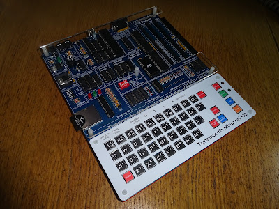
The production board has a few small changes, the button artwork has been updated, and there is new a perspex top plate and base.
Advertisements
The Minstrel 4D is available for preorder from The Future Was 8 bit. This will be a self assembly kit, using all through hole components. These should be shipping in 2-3 months. Update 2022-12-09 - Shipping Now
https://tfw8b.com/product/minstrel-4d-turbo-jupiter-ace-compatible-computer-kit/
Patreon
You can support me via Patreon, and get access to advance previews of projects like this and behind the scenes updates. This now also includes access to my new Patreon only Discord server for even more regular updates.
https://www.patreon.com/tynemouthsoftware