Tuesday, 5 September 2017

VIC20 Tape to Disk Conversion

This is an old post, preserved for reference.
The products and services mentioned within are no longer available.

Even though the VIC20 computer is a popular machine, there are still a lot of software titles which are not easily available.
Tornado is an example of this, as pointed out on twitter, quite a decent little game for the Unexpanded VIC20. Currently, there isn't a .prg file to allow it to be loaded more easily via an SD2IEC, so it's load from tape each time.
The tap file version of this game is essentially a digital copy of the data on the tape. This tap file can be used by emulators, but on real hardware it's not as easy, ideally there would be a prg file that could be loaded. I like a challenge, so I got the tap file for that game and tried it out.
It has a two stage loading process. The first program that loads shows a title screen, then the game itself loaded, you selected the number of players and away you go.
This was probably done to get around the limitations of the machine, the game was designed for an unexpanded VIC20, so there was only 4K to play with, so the code is split in two.
The first part is in BASIC, which shows the introduction screen and loads the second part from tape, with is 4K of machine code.
This code at the start checks where the screen RAM is located (address 0x288 or 648 in decimal), and moves it if necessary. The next few pokes are in the 0x900x range, which is writing directly to the VIC video chip. Writing those values to 36866 (0x9002) and 36869 (0x9005) puts it in 22 column mode, sets the video memory address to to 0x1E00 and selects character set 1. The Poke to 36875 (0x900F) sets the border and background colours to white.
The data at the end of the loader is a small bit of machine code which does the actual loading. The loop at line 200 pokes this into a spare location in RAM and then line 300 runs it.
(C:$0301) d 2a1
.C:02a1  A9 01       LDA #$01
.C:02a3  A2 01       LDX #$01
.C:02a5  A0 01       LDY #$01
.C:02a7  20 BA FF    JSR $FFBA
.C:02aa  A9 00       LDA #$00
.C:02ac  A2 00       LDX #$00
.C:02ae  A0 1E       LDY #$1E
.C:02b0  20 BD FF    JSR $FFBD
.C:02b3  A9 00       LDA #$00
.C:02b5  A2 CE       LDX #$CE
.C:02b7  A0 1F       LDY #$1F
.C:02b9  20 D5 FF    JSR $FFD5
.C:02bc  4C 00 12    JMP $1200
.C:02bf  00          BRK
This is from the monitor in the Vice emulator, which is handy for this sort of thing. The command 'd 2a1' disassembled code starting a 0x02A1 (or 673 in decimal as it was in the BASIC program). The code can be broken into three calls to kernal routines and a jump to run the start of code memory.
.C:02a1  A9 01       LDA #$01
.C:02a3  A2 01       LDX #$01
.C:02a5  A0 01       LDY #$01
.C:02a7  20 BA FF    JSR $FFBA
The three calls all follow the same pattern, load the three registers, A, X and Y with values then call a kernal routine. In this case, this is setting up a load operation, and sets the logical, first and second addresses. Here, they are all set to 1, so loads from cassette.
.C:02b2  A9 07       LDA #$07
.C:02b4  A2 A1       LDX #$A1
.C:02b6  A0 02       LDY #$02
.C:02b8  20 BD FF    JSR $FFBD
The second kernal routine is setting the load filename, in this case, A is 0, so X and Y are ignored, no filename is used, so just LOAD "".
.C:02b3  A9 00       LDA #$00
.C:02b5  A2 CE       LDX #$CE
.C:02b7  A0 1F       LDY #$1F
.C:02b9  20 D5 FF    JSR $FFD5
The third routine uses the previously set information to load from file into RAM. A load address is actually specified (0x1FCE) but it isn't used as the secondary address is set to 1 above, so it uses the load address from the file (just like LOAD"*",8,1 does).
.C:02bc  4C 00 12    JMP $1200
Finally, with the game code loaded, it jumps to the start of that code and runs the game. The address of 0x1200 is the start of the 4K internal RAM of the VIC20, so loading there has actually overwritten the BASIC loader program, which is why these few instructions were placed in a spare area of RAM (02A1-02FF) outside of the main 4K to avoid being overwritten.
That area of RAM is available in all states of the VIC20, unexpanded, 3K, 8K and more. This does run fine on an unexpanded VIC20, and there is no mention on the case or cassette, but the instruction leaflet says it needs +3K RAM. I'm here to tell you it doesn't need +3K RAM, but will run fine if you happen to have it.
The next step was to extract the loaded information. I went back to the .tap file and loaded the loader program into the Vice emulator. This time, I changed the number of bytes to poke from 29 to 26, so it didn't have the JMP $1200 instruction at the end. That meant it loaded the file, then stopped. I then entered the Vice monitor and saved the block of memory it had loaded.
s "tornado" 0 1000 1DFF
This writes the file "tornado" to device 0 (the host file system - use 8 for a disk image if you prefer), from 0x1000 to 0x1DFF, a 3.5K block that is available on both unexpanded and expanded VIC20s, all of which appears to be used. The s command adds the load address prefix to the file in the correct way, so to test this, you can use the following.
That appears to work, but ideally I want to modify the loader to load the data from disk. The loader code specifies device 1, so will still try to load from tape, even if the loader itself is loaded from disk. It's not just a case of changing the device number, a file name needs to be specified, so I have added that to the start of the data statements, so it appears at 0x02A1.
(C:$02d2) m 02a1>C:02a1  54 4f 52 4e  41 44 4f 00   TORNADO.
The code then starts at 0x02A9.
(C:$02d9) d 2a9
.C:02a9  A9 01       LDA #$01
.C:02ab  A2 08       LDX #$08
.C:02ad  A0 01       LDY #$01
.C:02af  20 BA FF    JSR $FFBA
The first function parameters need to be altered, this time to device 8.
.C:02b2  A9 07       LDA #$07
.C:02b4  A2 A1       LDX #$A1
.C:02b6  A0 02       LDY #$02
.C:02b8  20 BD FF    JSR $FFBD
The second function now sets the filename length as 7 characters, and says it is stored at 0x02A1.
.C:02bb  A9 00       LDA #$00
.C:02bd  A2 CE       LDX #$CE
.C:02bf  A0 1F       LDY #$1F
.C:02c1  20 D5 FF    JSR $FFD5
The third function is unchanged, and still has the unused load address.
.C:02c4  A9 01       LDA #$01
.C:02c6  20 C3 FF    JSR $FFC3
I have added a forth function call, this one closes the file after it has been loaded. Those four together are the equivalent of LOAD "TORNADO",8,1.
This modified code was hand assembled and converted into decimal and added to the data statements. What fun I had doing that. The final change was line 300 now runs the code at 0x02A9 (681 in decimal).
The final step was to make a D64 image. I used CBM Transfer to create a new empty D64 and copied the files in, loader first so it would be the default file, then the tornado program itself.
I tested that out in Vice and all was well, so time to try it on some real hardware, loading from an SD2IEC (via the Penultimate Cartridge menu).
I have sent the file to The Future Was 8 Bit (who originally requested it), here is his video of playing it on a real VIC20.


Sunday, 3 September 2017

Camputers Lynx 48K Repair

This is an old post, preserved for reference.
The products and services mentioned within are no longer available.

Here we have an Camputers Lynx 48K in for repair.
This is not a very common machine, and one of three almost identical models produced by Cambridge based Camputers (see what they did there?).
This model is 48K, other options were the same machine, but with 96K or 128K. Inside, there is quite a lot going on.
The plug in model is 8x4116 chips, giving 16K RAM.
Under the first 16K RAM board, there are another 8x4116 chips giving another 16K of RAM.
Finally, under the keyboard lead, there are another 8x4116 chips giving the last of the three banks of 16K, making 48K.
Presumably the other models had different combinations, 96K would probably be the two onboard banks of 16K and a 64K plug in module. Not sure about the 128K version, maybe two banks of 64K on board? The maximum would be 192K with two banks of 64K on board and a 64K module.
Driving all this RAM, is a Z80 running at 4MHz, with BASIC in two 8K EPROMs.
Video output is via a 6845 (same as the CPC464, BBC Micro, Commodore PET etc.). The COM8017 is a UART for the serial IO. The rest of the board is full of TTL glue logic.
Powering it on, there is nothing on the screen. Checking the power supply, all voltages are present. The reset line has pulsed correctly, and the clock is running, but there is no activity on the data or address busses.
One dead Z80 replaced with a new one. As was pointed out on twitter recently, isn't it great that the Z80 CPU is still in production.
Powering on, we now have a screen, a nice Lynx logo and a cursor. The cursor flashed a few times, then stopped, and wouldn't respond to the keyboard. I cycled the power a few times, and got the same thing. On the forth go, it beeped and the cursor kept flashing.
It then ran long enough to type this in, but locked up before I could type run. My first thought for intermittent problems like this would be the RAM. The 4116 isn't known for it's reliability, and there's an awful lot of them in there.
I fired up my '4116 tester' and we through all the socketed chips on board. and all seemed fine. The ones on the plug in module were soldered in, so it didn't want to test those until I had rulled out everything else. I tried running it with that module removed, but I got a green screen on power on, and no beep.
The next thing to test was the EPROMs. One read correctly, but the other didn't match the image I had from the internet (Russell Davis archive of Lynx related info).
I then wasted a lot of time trying to work out what the few byte differences were. The 48K/96K/128K versions had slight differences, so I thought this might have been the wrong one of those, or an earlier / later version of the archived one.
What I should have done and didn't do until much later, was retest it several times, and observe that it kept changing.
I dug out a similar EPROM and burned a new copy of the correct ROM image, and it was back up and running.
This time it kept running, and I didn't see any further problems.
I have received some photos from the owner when they got their Lynx back.
Include some games he wrote for the Lynx 34 years ago.
He is now going through all his old tapes archiving all the software. That's great to hear as there doesn't seem to be much around for the Lynx.
Read more about that on his blog.

Sunday, 27 August 2017

Commodore PET video RAM faults

This is an old post, preserved for reference.
The products and services mentioned within are no longer available.

This seems to be quite a common fault throughout the range of Commodore PET machines, so I thought I would roll up several repairs into a single post.
On power on, you get a screen full of characters, and there is something that looks about right, but all the letters look wrong.
If you look closer, you can see that in this case, the numbers and some of the letters are right. This is what it should say.
Now we need to do a bit of maths. First you need a table of the PETSCII character set (which is not quite the same as the ASCII one). This screen is generated by my PET Diagnostics board, and is quite handy for this.
Look up the values of some of the characters which are displaying correctly and incorrectly and look for a common factor.

Expected
Hex
Binary
Displayed
Hex
Binary
R
12
0001 0011
R
12
0001 0011
E
05
0000 0101
U
15
0001 0101
A
01
0000 0001
Q
11
0001 0001
D
04
0000 0100
T
14
0001 0100
Y
19
0001 1001
Y
19
0001 1001
3
33
0011 0011
3
33
0011 0011
*
2A
0010 1010
:
3A
0011 1010

From that it can be seen that the characters all being displayed all have bit 4 set, even the ones that shouldn't have bit 4 set. So the RAM chip which stores bit 4 is faulty (or sometimes the buffer that writes into it, or the latch which reads out of it).
On earlier 40 column machines (usually the ones with 9" monitors), there are two 2114 RAM chips. One handles bits 0,1,2 and 3, and the other bits 4,5,6 and 7.
Later CRTC based 40 column machines, there are two 2114 chips next to the empty spaces where the 80 column circuitry would go.
On 80 column machines, all four RAM chips are populated. Each pair handling alternate characters, so if you have the same bit 4 fault on an 80 column machine you would see alternating faulty characters.
You can see the first, third, fifth etc. characters are all correct, and the second, forth, sixth etc. have bit 4 stuck high as above.
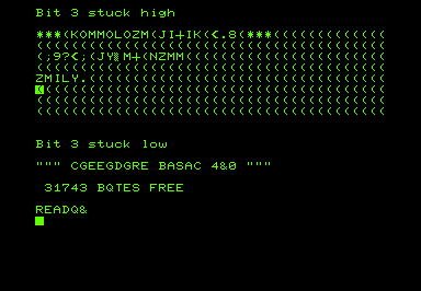
I have written a program to simulate bit faults in the video RAM:
You can also see whole RAM chips failing, so you all four bits in the upper or lower nibble are stuck.
Finally, if both RAM chips are faulty, you get a nice chequer board pattern or a screen full of @'s.
The 2114 RAM chips used on most PETs are still available, but the 6550 RAM chips used in some of the earliest 2001-8 models are more difficult to locate. You can just see them under the dust.
This 2001 appears to have one dead chip, you can see the same O's and /'s pattern in the simulations above.
Swapping the chips around shows the opposite problem, so it is definitely a faulty chip.
I have built a module which can plug in and replace both of those chips.
I haven't listed these for sale, but if anyone needs one, let me know.
In this case, once the display was working, the RAM count was short, one of the main bank of RAM was faulty.
The spare working video RAM chip was used and the full 8K restored.
It is worth noting that a common fault on the 6550 RAM chip is the enable lines, there are several of them and the seem to fail in a way that enables the chip all the time, drowning out or fighting with whichever other chips should be active at the time.
When used as video RAM, the enables are not required, so you can sometimes shuffle the chips around so the ones with faulty enable lines are used as video RAM. I didn't have any spare dust to reapply to these chips.
Here is the same sort of fault, this time on a TRS80 Model I. Unusually, it only affects part of one line, which is showing '£' characters.
The characters all work when typed anywhere else on the screen, just the £ sign appearing on the end of that line.
Typing into that area shows characters are being modified, and the space is being shown as a £, in the same way as the space on the PET was shown as @ or / etc. depending on the fault.

Expected
Hex
Binary
Displayed
Hex
Binary
q
31
0011 0001
1
71
0111 0001
r
32
0011 0010
2
72
0111 0010
space
20
0010 0000
£
60
0110 0000
*
2A
0010 1010
j
6A
0110 1010

These all point to bit 6, which on the TRS80 is a bit unusual as the video RAM is made up of 7 chips with bit 6 unused. Later an eighth chip for bit 6 was bodged on with a piggy back chip.
With that replaced, the TRS80 was back to normal.
Whilst on the subject of video faults, I may as well mention another few oddities. This PET showed only a flashing white cursor, which moved around as you types, but no characters.
This was down to a dead character ROM.
The character ROM is also to blame if you get characters that aren't quite right, such as the extra bar on the E here.
On most PETs, a 27C16 or 2816 can be used, but for 2001-8's with 6540 ROM chips, I have an adapter.
With that, the video RAM replacement and a ROM/RAM board, you can get rid of all the 6540 and 6550 chips and have a 2001 PET which should be considerably more reliable (and less than half the power consumption).
A permanently inverted picture can be caused by a few things, it bit 7 fault can do that, but in this case it turned out to be a 74LS74 flip flop.
The same machine also developed a screen which was full of stripes, even with the character ROM removed, so that was narrowed down to the 74LS165.
Both replaced and the machine is back to normal.
I think that's about all I can say about video faults on the Commodore PET. Congratulations if you got this far, by the way.