Thursday, 23 February 2017

Minstrel ZX80 Clone Issue 2.3 Boards

This is an old post, preserved for reference.
The products and services mentioned within are no longer available.

The Minstrel ZX80 clone boards and kits are back in stock in my Tindie store.
These are now issue 2.3 boards which have some minor tweaks to the connector and hole alignments when used in a ZX81 case.
The Minstrel is a fully compatible ZX80 clone that can run the original 4K ROM BASIC, or the later ZX81 style 8K ROM BASIC. It is not fully compatible with the ZX81 due to the lack of NMI slow mode, although this is something I am working on for a future version.
These follow the original ZX80 schematic and use the same parts where possible. The only changes being the RAM is upgraded to 16K using a modern RAM chip, the ROM is a 27C64-27C512 EPROM and there is a composite video output with an additional circuit to add the missing backporch pulse to the composite video signal and clean it up for use on a modern TV or monitor. I've made a minor change to the values of the resistors which combine the video signals.
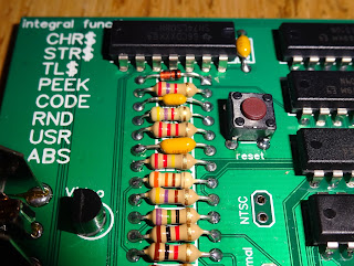
The values of the second and third resistors from the top have changed from 2K2 and 1K5 to 4K7 and 2K2. The new values are marked on the silkscreen.
There is also a minor error where two pins are floating that should be pulled high. They work correctly as is due to internal pullups in the chip, but there should be a connection between pin 13 and pin 14 of the 74LS86. This can be done with a solder blob on the back of the board, or a small wire inserted between the pins before soldering.
This is designed to be used in a whatever enclosure you like (see my previous post with some other examples of ZX80 Clone builds), or can be fitted into a ZX81 case. Here I have a pretty beat up ZX81 case which had some marks on the lid and needed a new membrane. I removed the old membrane and sanded that down the lid to remove the marks, and also sanded off the embossed ZX81 letters.
The next step was to spray the case white, ZX80 style.
This came out remarkably well, with all the detail in the Sinclair logo coming through clearly, and no sign of the original marks or the ZX81 lettering.
The case was ready for a new membrane. I am going to use the 4K BASIC on this build, so it needs the blue ZX80 style keyboard, which has different keyword and symbols to the grey ZX81 style.
Membranes are currently only available for the ZX81, so I have started with one of those.
I have had some overlays printed to match the ZX80 layout which can be stuck over one of these ZX81 membranes to give a ZX80 style keyboard.
That is installed as normal, and you get something which is starting to look like a ZX80.
Inside the membrane tails are ready to connect to the board.
I usually flip it over to make the it easier to connect up.
The board is flipped back and the holes lined up.
The two holes with white circles around should be screwed in now, the others pass through the back of the case.
I masked off the EAR/MIC/9V DC labels before painting, to leave the recessed connector section black.
The case can now be assembled and the keyboard tested.
Yes, all the keys are working, and all the keywords are in the right place.
The picture is nice and clear on a modern LCD TV.
The final touch was a ZX80 logo for the case.
That's turned out better than I had expected, a very nice looking ZX80 clone.
It stands up well against an original ZX80.
These are available as bare PCB, as a kit form and as a build up board from my Tindie store and The Future Was 8bit. There are a various kit options, but too many options to list them all, if you want something different, contact me and I'll see what I can do. Do you need sockets, connectors, 7805 or switch mode, which keyboard etc. I will also be building a few for sale as complete boards or complete units - again, let me know what you want.

UPDATE:
I am now shipping V2.4 PCBs, which are also available in blue silkscreen.

UPDATE 2:
I am now shipping V2.5 PCBs, also in green or blue. It seems I haven't got any more creative with my photos since the last one was taken.

2022 Update: At the time of writing, there are still a few Minstrel 2 (ZX80) and Minstrel 3 (ZX81) kits available from  The Future Was 8 bit but those are the Final Edition kits, there are unlikely to be any more.

Sunday, 19 February 2017

ZX Spectrum Issue 2 Repair

This is an old post, preserved for reference.
The products and services mentioned within are no longer available.

As part of the testing of the DivMMC future, we tried to use a range of machines of all different types and conditions. Some pristine and working perfectly, some upgraded and recapped, some in pretty poor condition.
This was a fairly bad one from my 'broken' pile. This is an early-ish issue 2 board which arrived in this condition inside a 48K rubber key Spectrum from ebay.
The first obvious issue is the missing Z80 CPU, not a standard socket, so it's probably been repaired in the past. Also note the ROM is marked with an X, presumably someone has tested this and found it not working.
Like most issue 2 boards, the transistor mod has been done to the CPU. However this ones has not had the clock mod, this is the original version of the clock circuit with the diode and 3K3 resistor, and no pullup on the clock line. See my previous post about reverting a board to this state and earlier.
As well as the cross on the ROM, there are also marks on one chip in either set of RAM, presumably theses had been identified as faulty as well.
Looking under the PCB, it is obvious the Z80 has been replaced, and also the 74LS157 next to it, although the chip and socket look identical to the one next to that.
At the top, there seems to be some track damage, and that flux is a bit nasty.
The soldering is a bit inconsistent, so I really need to remove this.
Looks a lot better with the socket desoldered and the flux cleaned up. One of the reasons I dislike sockets with a covered base is that you can't see what condition the board is in underneath it. I've lifted a few like that and found gouges in the board from removal of the previous chip which had broken tracks so it was never going to work.
This isn't too bad, a few suspicious looking tracks, but continuity tested OK once the socket had been replaced and solder had flowed on both sides of the board.
With a new Z80 installed, the next thing was the ROM, I had noticed under the heatsink that the jumpers were set for H, a Hitachi ROM, but the chip installed was an NEC, which should have the N jumpers installed. The Hitachi ones are less common, and I didn't have a spare to hand, so I changed the links to N.
With that the machine still didn't boot, but I was now able to run a memory test cartridge which showed up a fault in D5. This is an issue 2 board, so obviously, the colour is way out. I'll address that later.
Looking at the RAM, the IC that handles D5 is the one which was marked as faulty.
I have to agree, IC11 is probably faulty as that is the chip which provides 16Kbits of RAM on D5.
With the 4116 in IC11 replaced, the memory tests now passed, and I could adjust the colour. The D5 chip in the upper bank was also marked as bad, but seems to test OK.
With the RAM tests passed, time to try the ROM and see if I can get into BASIC.
No problems with the ROM either, which is unusual as I have had a lot of issues with NEC ROMs, more on that in a later post. I presume this board originally had a Hitachi ROM and that was swapped with another Spectrum along with the CPU. The ROM was probably marked as bad when actually it was just the jumpers were set wrong.
That one didn't turn out too bad.
  • Some track damage and ugly soldering on the CPU socket
  • Missing CPU
  • Wrong jumper links for the ROM
  • One RAM chip replaced
  • The usual issue 2 colour correction. 
  • New membrane
  • Cleaning the edge connector
  • Composite video modification
Far fewer parts than were actually marked as faulty.
The important question now the board has been resurrected, is does the DivMMC Future work with it?
Well, of course it does.
Someone asked on twitter about Jet Pac, yes, that runs fine. I found there were a few flaky copies on the internet, so I saved a .z80 snapshot from the fuse emulator, and I have been using that without a problem.
I saved after I had selected Kempston joystick, so I can just press 5 to start.
I did try some other boards and things like the interface 1 with this Spectrum, but I couldn't get them to work. The clock modification done to later issue 2 boards may help, but the DivMMC future works without the need for that.
I have been testing using early prototype and release candidate DivMMC future units in 3D printed cases.
I am sure The Future Was 8 Bit would like me to remind you that the final units will come in injection moulded cases like his SD2IEC drives and the VIC20 Penultimate Cartridges.
N.B. the preorders will come with a preloaded SD card, but sadly the biro is not included in the current offer. If the lack of a yellow biro is not a deal breaker, you can preorder a DivMMC future with SD card now.

2022 Update: The production version of the DivMMC future is now available from The Future Was 8 bit