
This is an old post, preserved for reference.
The products and services mentioned within are no longer available.


Block
|
Address Range
|
Use
|
0
|
0000 - 1FFF
|
Internal 5K RAM + Cartridge RAM1/RAM2/RAM3
|
1
|
2000 - 3FFF
|
Cartridge BLK1
|
2
|
4000 - 5FFF
|
Cartridge BLK2
|
3
|
6000 - 7FFF
|
Cartridge BLK3
|
4
|
8000 - 9FFF
|
Video / IO space
|
5
|
A000 - BFFF
|
Cartridge BLK5 (autostart)
|
6
|
C000 - DFFF
|
BASIC ROM
|
7
|
E000 - FFFF
|
KERNAL ROM
|
Block 0 contains the internal RAM, and can be expanded with an additional 3K from the cartridge port (although not with this cartridge). Block 4 is video RAM and I/O space, and blocks 6 and 7 contain the system ROMs. That leaves blocks 1,2,3 and 5 for ROM cartridges. Block 5 is special in that it is checked on system startup to see if it contains a bootable ROM, if it does, that will be started instead of the normal BASIC. These cartridge PCBs can be used to provide a single block (8K mode), or two blocks (16K mode). I did look at adding 4 block (32K mode), but as far as I know, Cheese and Onion is the only 32K cartridge out there, so you should just buy one of those instead.


8K Mode

A15
|
A14
|
A13
|
27C64
|
28C64
|
27C128
|
27C256
|
28C256
|
27C512
|
0V
|
0V
|
0V
|
-
|
-
|
-
|
-
|
-
|
ROM 1
|
0V
|
0V
|
5V
|
-
|
-
|
-
|
-
|
-
|
ROM 2
|
0V
|
5V
|
0V
|
-
|
ROM 1
|
-
|
-
|
ROM 1
|
ROM 3
|
0V
|
5V
|
5V
|
-
|
ROM 1
|
-
|
-
|
ROM 2
|
ROM 4
|
5V
|
0V
|
0V
|
-
|
-
|
-
|
ROM 1
|
-
|
ROM 5
|
5V
|
0V
|
5V
|
-
|
-
|
-
|
ROM 2
|
-
|
ROM 6
|
5V
|
5V
|
0V
|
ROM 1
|
ROM 1
|
ROM 1
|
ROM 3
|
ROM 3
|
ROM 7
|
5V
|
5V
|
5V
|
ROM 1
|
ROM 1
|
ROM 2
|
ROM 4
|
ROM 4
|
ROM 8
|
In most cases, the easiest option is to set all three to 5V and place the image in the top 8K of whichever ROM chip is being used.

16K mode
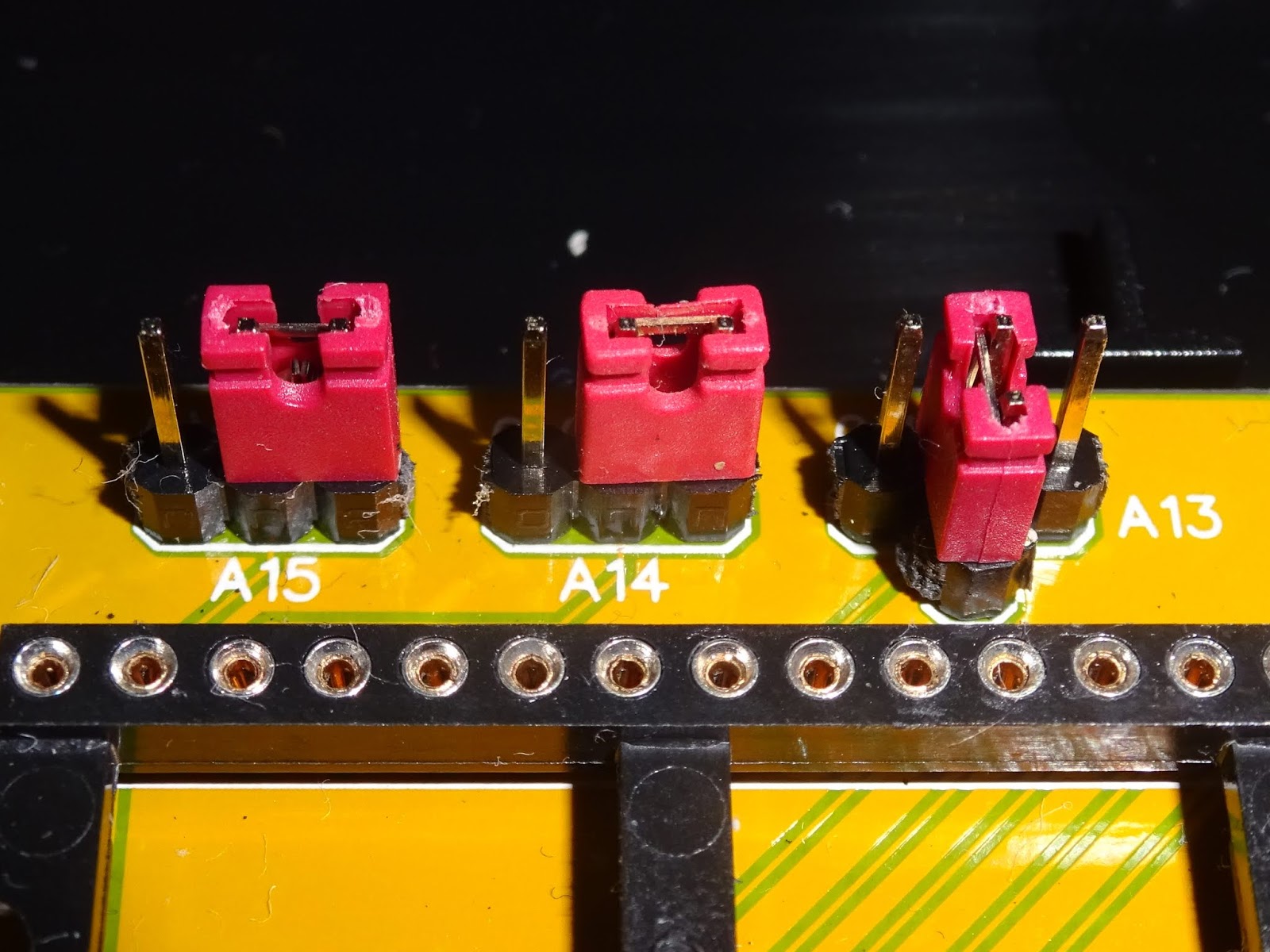
In 16K mode, the 74LS00 needs to be fitted (as does it's associated decoupling capacitor). The 8K/16K link is set to 16K mode, and two blocks need to be selected. The left hand block of jumpers selects the block for the lower 8K of the 16K ROM image. The right hand block selects the upper block. The upper block is normally 5, but the lower varies between software houses. This shows blocks 1 and 5 selected (this time using jumpers rather than wire links) and the 74LS00 fitted.
A15
|
A14
|
A13
|
27C128
|
27C256
|
28C256
|
27C512
|
0V
|
0V
|
16K
|
-
|
-
|
-
|
ROM 1
|
0V
|
5V
|
16K
|
-
|
-
|
ROM 1
|
ROM 2
|
5V
|
0V
|
16K
|
-
|
ROM 1
|
-
|
ROM 3
|
5V
|
5V
|
16K
|
ROM 1
|
ROM 2
|
ROM 2
|
ROM 4
|
Here I've fitted jumpers, but wire links can be used as before.
Installation


2022 Update: More recent versions of the VIC 20 cartridge PCBS are available from The Future Was 8 bit Yellow didn't last long, they are blue now.